
PS5 Controller
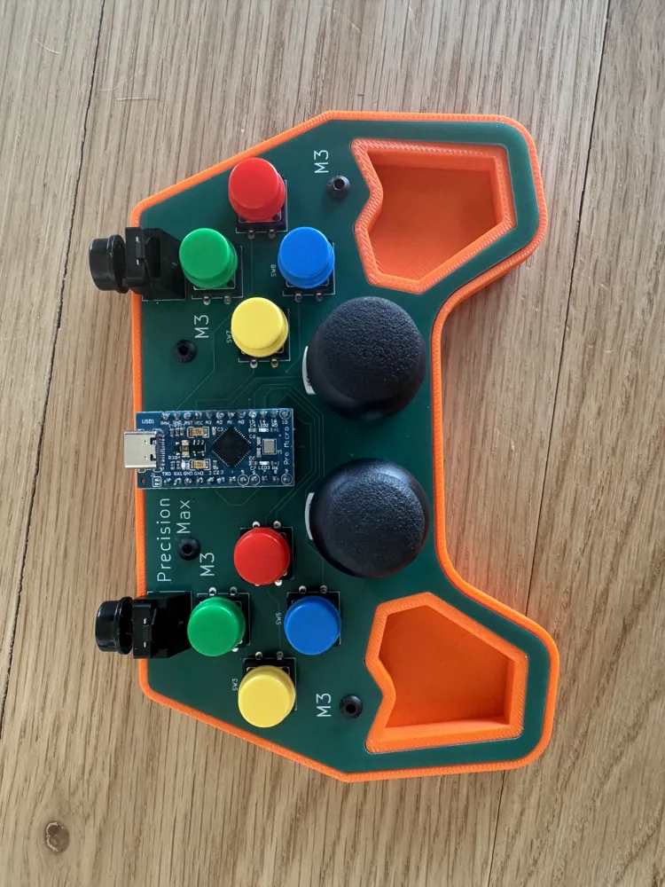
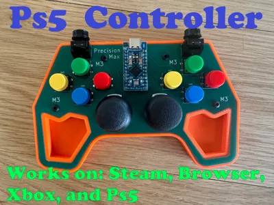
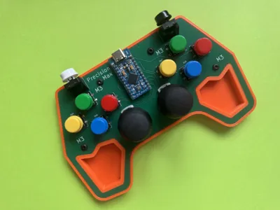
Print Profile(1)
Description
Hi everybody
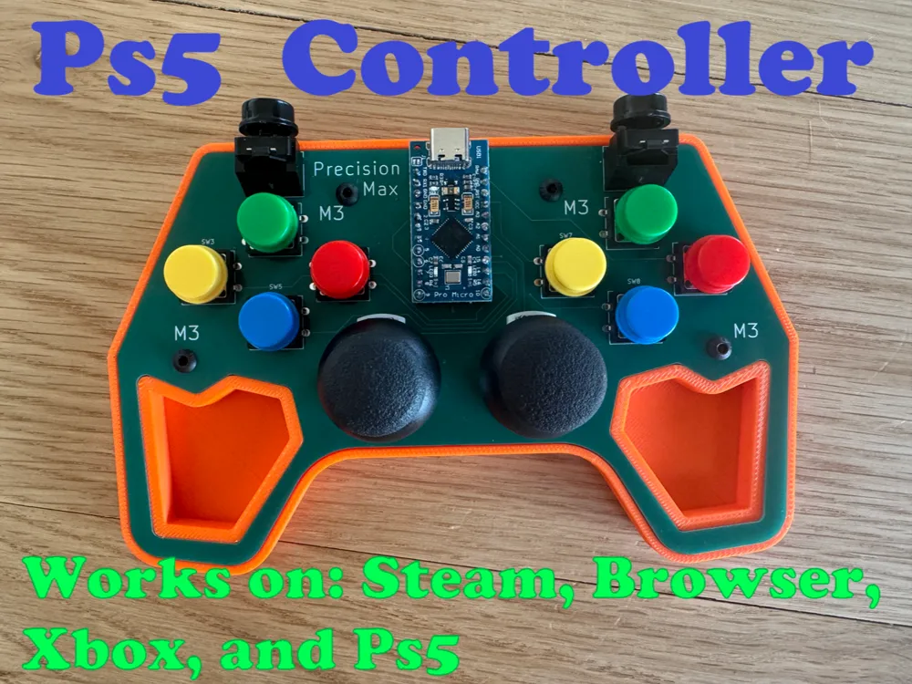
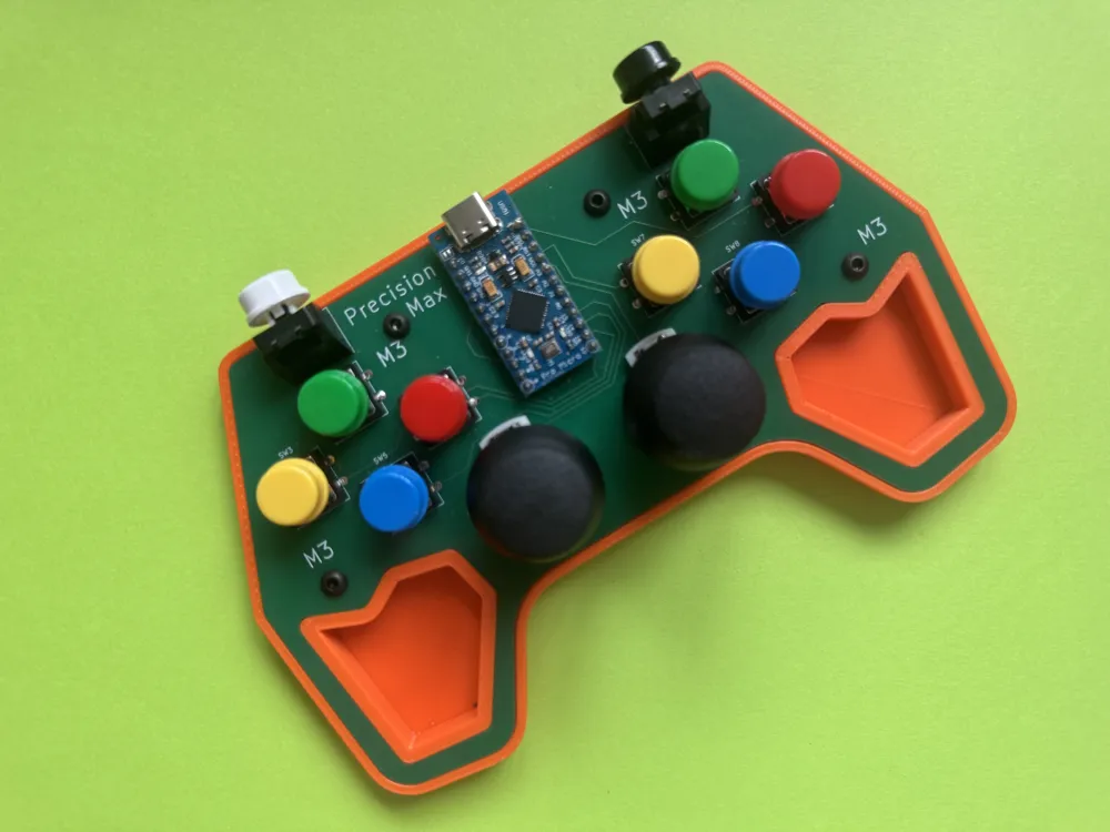
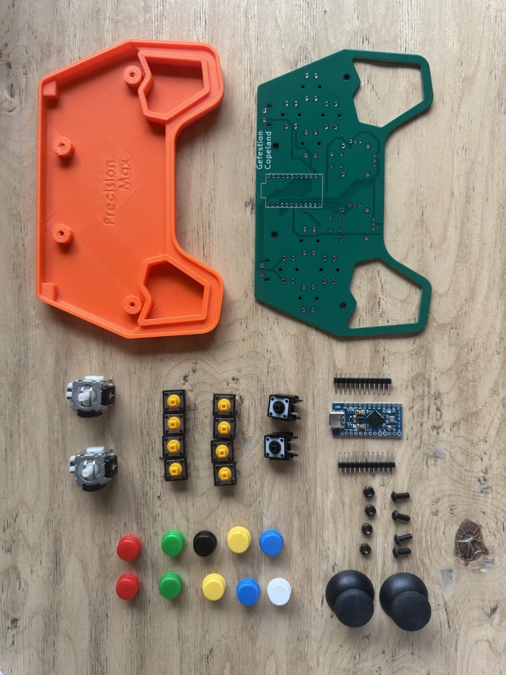
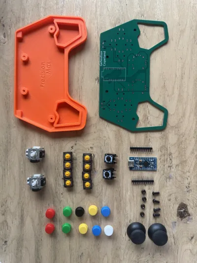
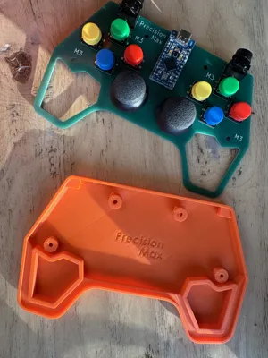
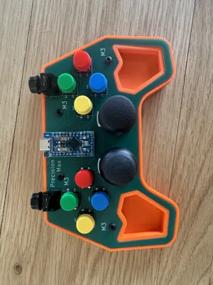
I worked on this PS5 controller for a month. Please cut me some slack I am only 14 so still learning. Anyways, here is the direction for assembling. First let me list all the components and then we will get into how to assemble it. Note - you need a USB C cable to connect the PS5 to the computer.
PS5 Replacement Joystick: https://amzn.to/4vIzbDG
Vertical Pushbutton: JLCPCB SMT Parts Library & Component Sourcing
Now for these they are pretty rare so you can't buy them on Amazon, but still cheap off sites like JlcPcb or SnapEDA.
Horizontal Pushbutton: https://amzn.to/4cxQEFQ
Arduino Pro Micro: https://amzn.to/3OR4LOR
M3 Screws: https://amzn.to/3OfruE9 They have to be smaller than 8mm, so anything 8 or below 8mm will work.
Okay so you need to order the PCB from JLCPCB here is the GitHub that contains both the code and the Gerber ZIP.
GitHub: https://github.com/geco11/PS5-Controller-PCB
Joystick.h Library: https://github.com/MHeironimus/ArduinoJoystickLibrary
And download the ZIP.
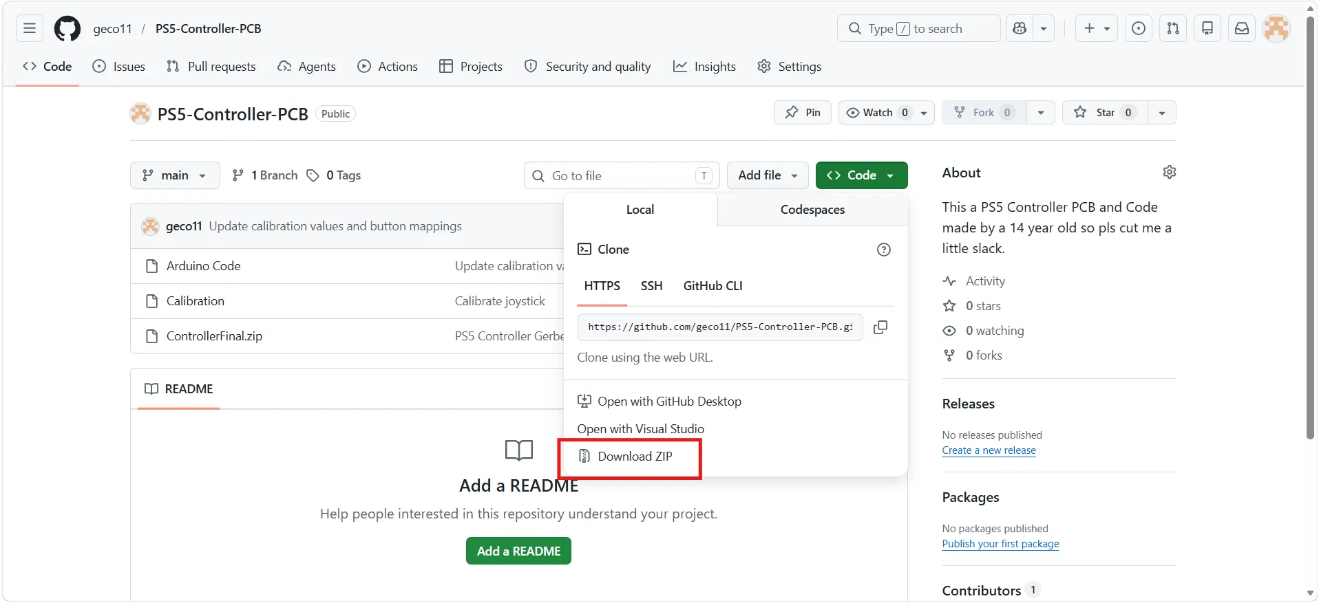
Open the file and when you see ControllerFinal.zip
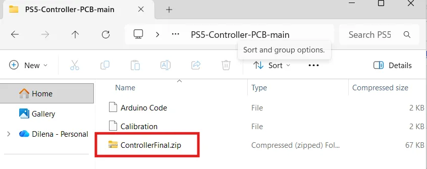
Open JlcPCB they will manufacture the PCB for only 7$ a pack. this is a bigger PCB. click on instant quote and you will see
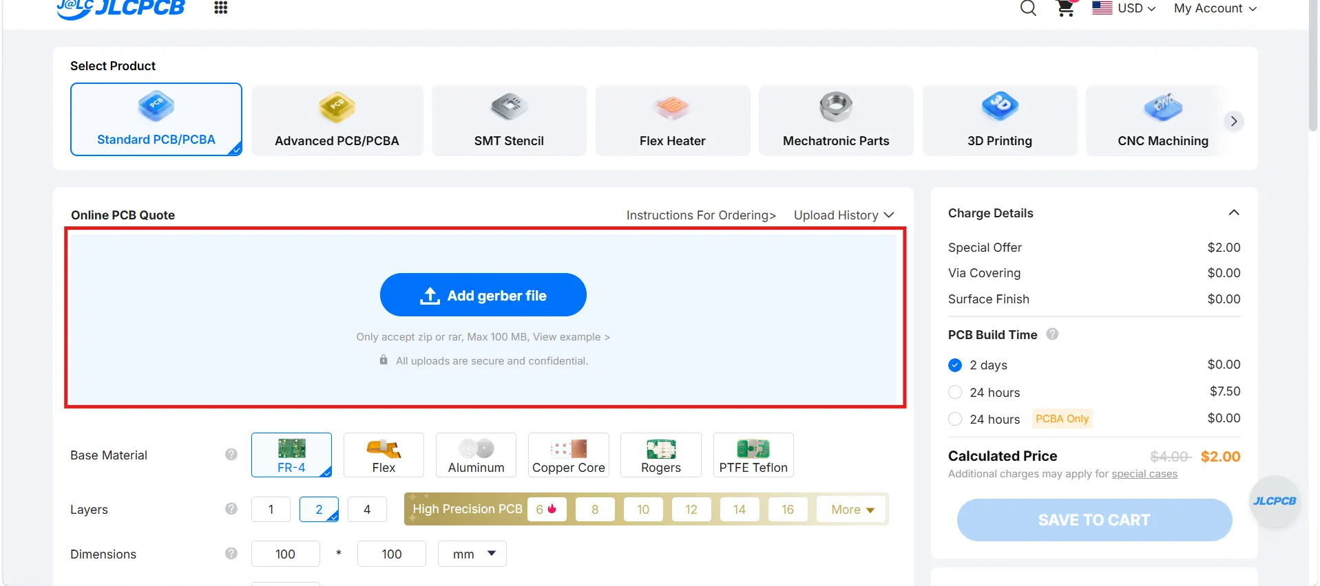
Drag the Zip into the box. you don't need to change any settings. I recommend changing your shipping method. the default one is 29$ to Global Standard Direct Line or your one account with UPS and DHL I use UPS and it is only 3 dollars. arrives in less than a week.
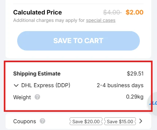
Now just proceed to checkout and order it. wait a week to get it delivered and… we can procede to the assembly!
its important to solder all the components to the top side of the PCB - you should see PrecisionMax and M3.
Solder the pins to the Arduino. I used a breadboard to hold the pins so it is easier to solder it and pins are guaranteed to be perfectly straight.
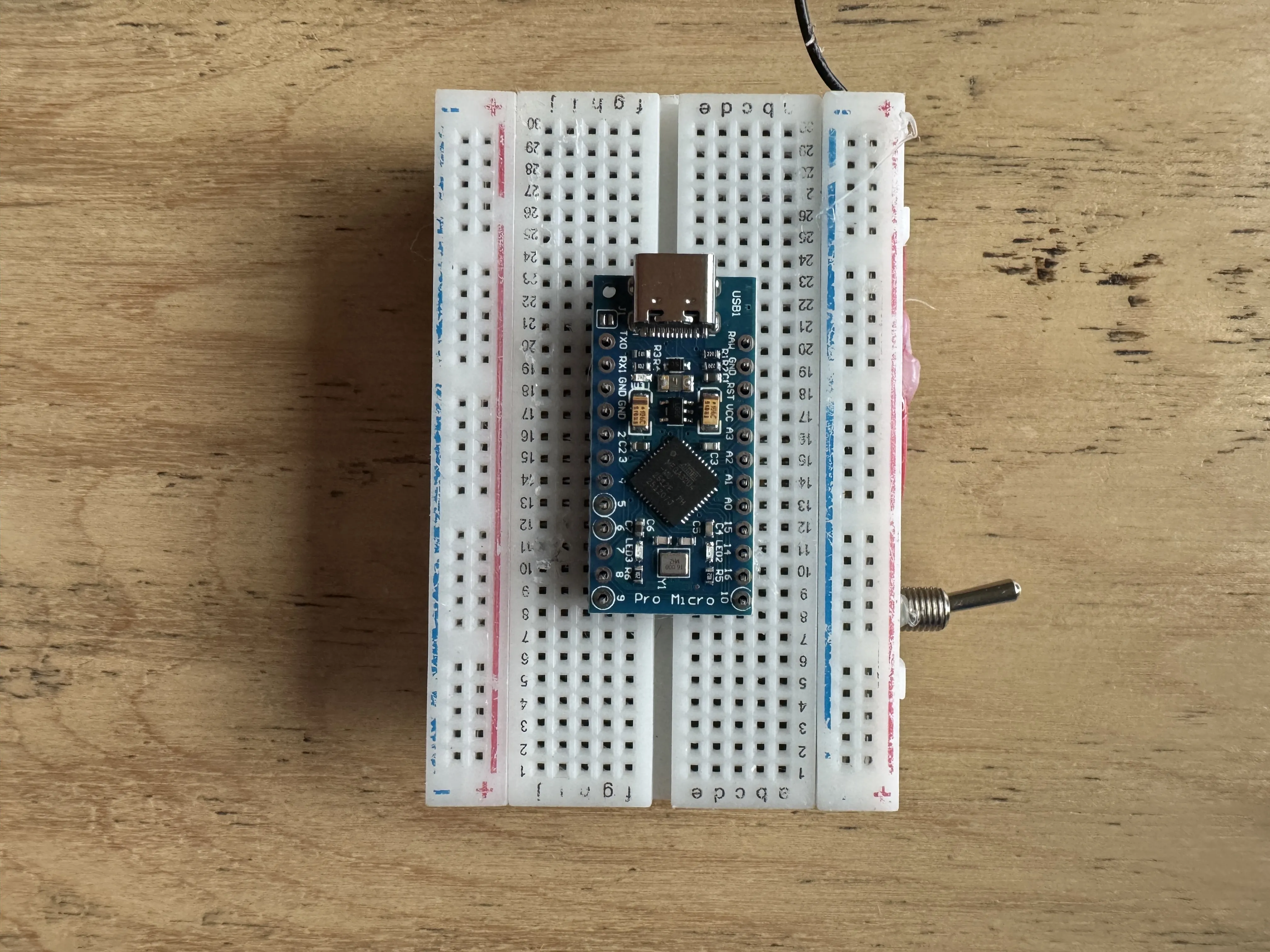
Once you finish - solder the 8 horizontal pushbuttons to the PCB push them down a little to make sure they are laying straight on the PCB. Make sure you don't put any pushbutoons on yet, because if you accidentally hit one with your solder then you will ruin the pushbutton. When your done with solder the two joysticks you will have to bend the potentiometer pins a little bit
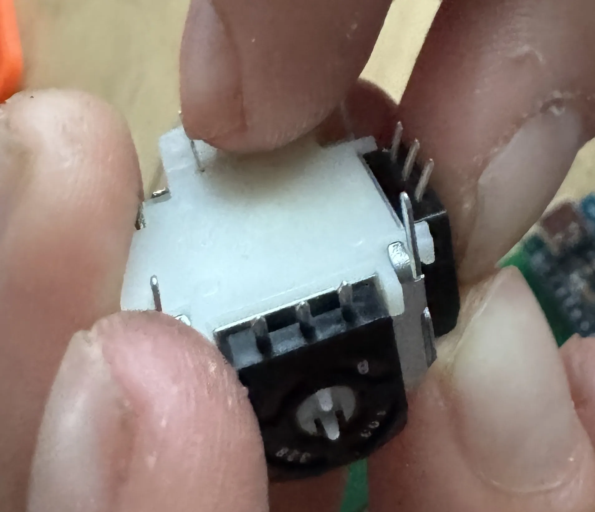
Also make sure to press down the pushbutton on the joystick and then solder all the pins of the joystick to the board.
also solder the top vertical buttons to the board. to connect the plastic buttons to the 2 vertical trigger pushbuttons - add a tad of glue to the pushbutton and connect the button.
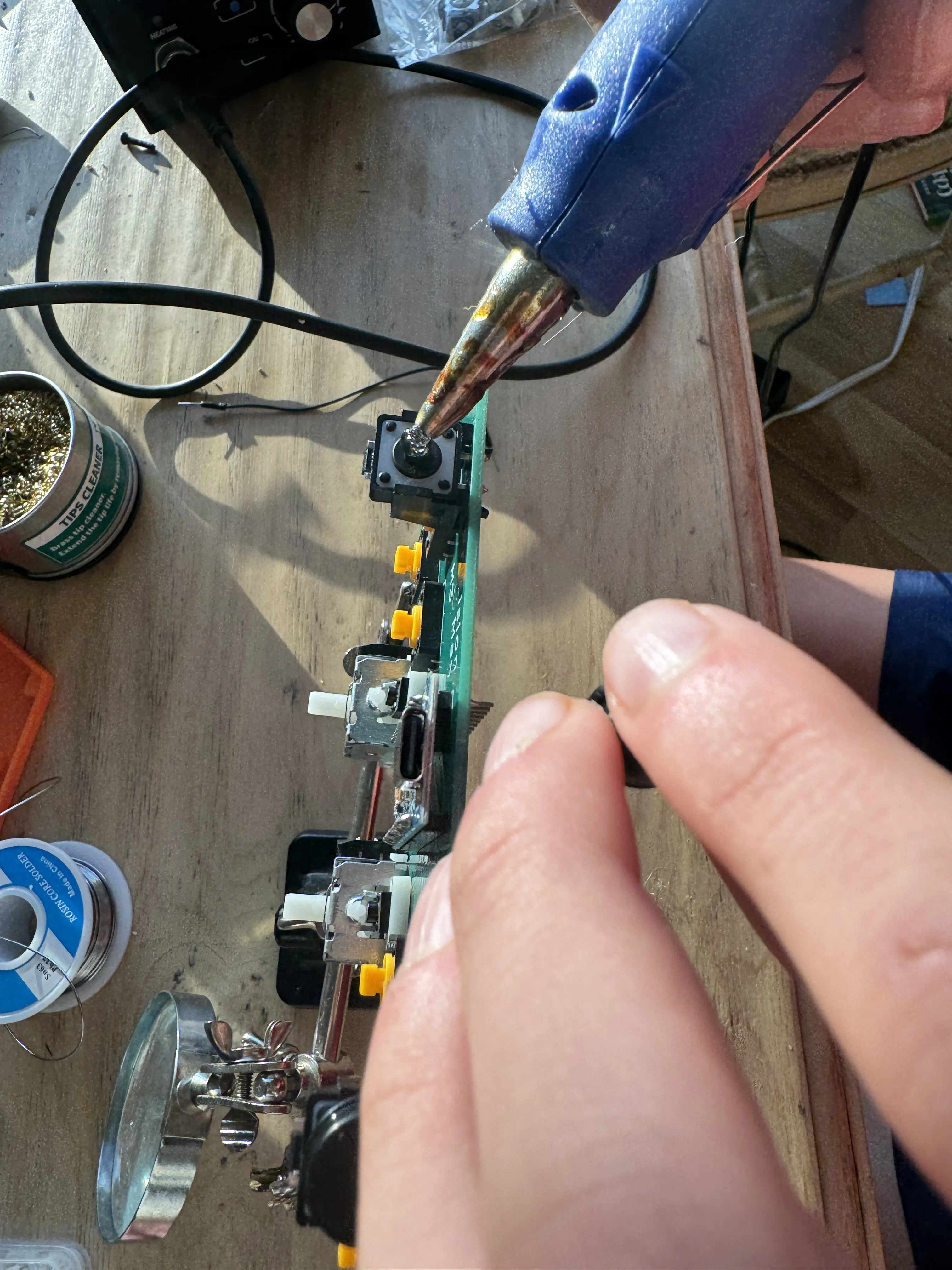
connect the rest of the pushbuttons to their plastic buttons. For the joystick caps if you don't have any lying around than you can just order some from amazon.
Next up comes the coding - open the github and open both of the codes again. Open the Calibration code and the Arduino Code in Arduino IDE . run the Calibration program. for that open Serial Monitor and follow its instructions. Then you will get a piece of the code and you will have to replace this part with the new part of the code
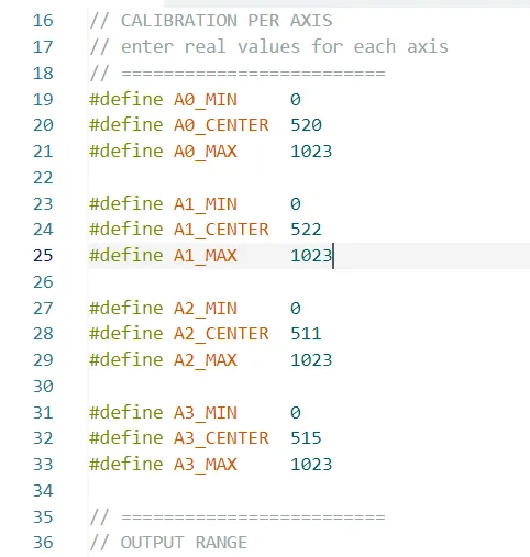
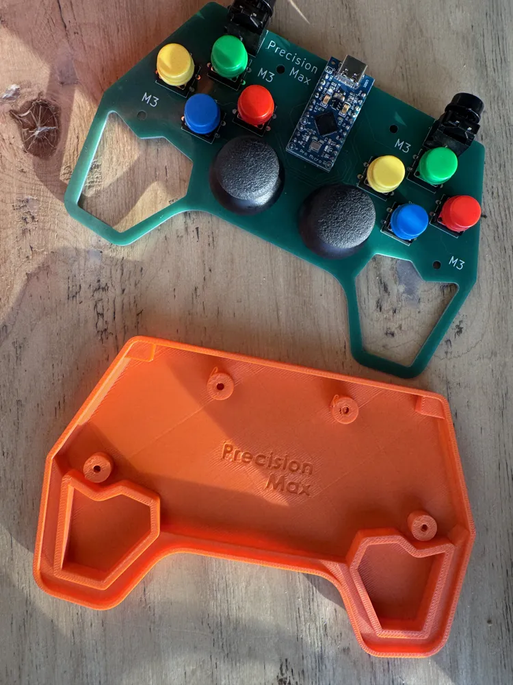
After replacing this part of code in the Arduino code file with the one you got in serial monitor. download the joystick library which I linked next to my GitHub. go to Sketch→Include Library→Add .ZIP libraries and choose the Joystick library and you all set! to check if it works visit https://controllertest.io/ . And now you can screw the case to the PCB using 4 M3 screws.
License

You shall not share, sub-license, sell, rent, host, transfer, or distribute in any way the digital or 3D printed versions of this object, nor any other derivative work of this object in its digital or physical format (including - but not limited to - remixes of this object, and hosting on other digital platforms). The objects may not be used without permission in any way whatsoever in which you charge money, or collect fees.


Comment & Rating (33)