Project Babble - "Raspberry Macaron"


Print Profile(0)
Description
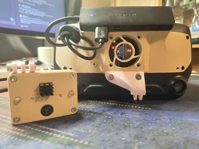
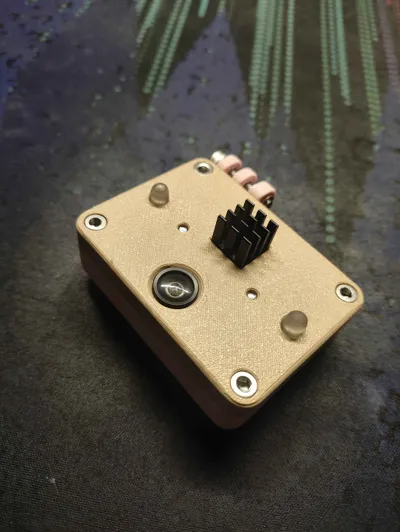
"Raspberry Macaron" is a case for Project Babble (face/mouth tracking project), housing a XIAO ESP32-S3 Sense with a OV2640 IR camera module.
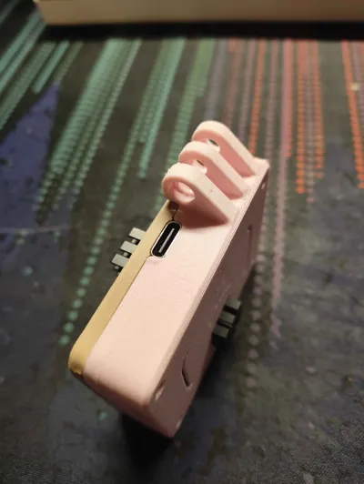
This case is meant to be easy to print and easy to assemble, while providing secure mounting, and a top facing USB-C port. No supports are necessary for any of the models.
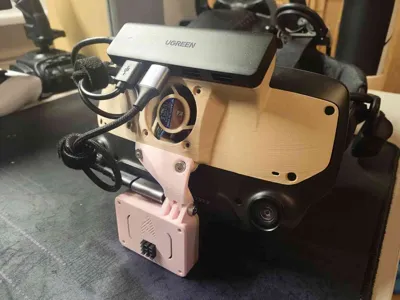
I have added a “mount base”, which can be used to make your own base for your specific headset, without needing to create the mounting interface itself.
The case is specifically meant for the following Project Babble configuration:
- XIAO ESP32-S3 Sense
- OV2640 160° FOV IR Camera (850nm)
- 2x 850nm IR LEDs, 5mm
- 2x 82Ω Resistor for power for LEDs from the 3.3V pin
It may work for a couple of other configurations as well, but it was not intended for them.
You can find more information about the configurations here: https://docs.babble.diy/docs/hardware
For the case you will need the following screws, and single nut:
- 4x M3 8-12mm (For the case corners)
- 2x M3 5mm (For the MCU holder)
- 4x M3 5-8mm (For the camera holders)
- 1x M4 16mm (For the mount)
- 1x M4 Nut (Also for the mount)
You will also need the two heatsinks that came with your XIAO ESP32-S3 Sense.
Depending on your mounting solution, you may also require a 90° USB-C adapter.
Printing information:
All of the pieces should be printed flat on the bed. The mount base is not ready to be printed without modification, you need to make your own mount for your specific headset.
You will need two camera holder brackets, one for each side.
Assembly guide:
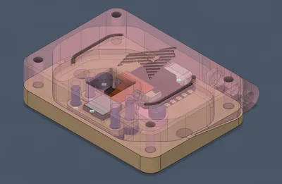
- Add your MCU to the bottom of the case, where the “indent” is. It should fit relatively snugly, but it will fit inside the groove entirely.
- Add the MCU holder in a way, where the “ears” of the holder overlap the MCU corners by a bit. Screw them in with the 5mm length M3 screws.
- Push the two LEDs into the larger circular holes of the bottom. They should be press fit, and should not be loose.
- Move onto the top of the case, and place your camera module into the rectangular slot, where there is a little “shelf” for it to sit on. (You can remove the camera module from the ESP32 for easier assembly).
- Use the two camera holders, one on each side of the camera, and screw them in with the 5-8mm length M3 screws, in a way where the camera is held snugly in place.
- If you had separated the camera module from the ESP32, reconnect it in a way where the ribbon cable exits towards the USB-C port.
- Now close up the case, the ribbon cable should create a 180° loop, but it should NOT be kinked in any way. There is enough space in the case for it to not require a very sharp fold. The two halves should interface together nicely.
- Screw in the four 8-12mm length screws into the corners of the case, securing the two halves together.
- Apply heatsinks to both, camera and MCU, fitting them through the square holes. Press down relatively well to ensure that they seat against the metal well, but don't apply too much pressure.
- Add the M4 nut to the hexagonal hole in the mount. It may take some effort, as not all M4 nuts are made in the same dimensions.
- Add the M4 screw, especially if the M4 nut is loose. You'll want to take it out later, when mounting the tracker.
Comment & Rating (0)