X45 Sprite CR Touch Probe Zero Y-Offset Mount v1.1 (Ender-3 S1 Pro and similar)
X45 Sprite CR Touch Probe Zero Y-Offset Mount v1.1 (Ender-3 S1 Pro and similar)


Print Profile(1)

Description
Update 25/08/2023
v1.2 added - access for heat break setscrew created, small amount of material added on the fan-side of the grille near the bottom to ensure proper clearance to heatsink fan.
Update 11/04/2023
v1.1 added - probe bracket added with improved tighter fit, hole position for long rear screw corrected (the position of the hole on the pre-remix models were off). The probe should sit a little higher - ensure you check probe offset again if you update your bracket, otherwise you might have a nozzle crash. Files renamed, Marlin config info added, X offset corrected from -44mm to -45mm.
Background
Some Ender 3 S1 and S1 Pro printers that ship have issues with getting a good first layer after auto bed mesh. This can be caused by the y axis not moving in a perfectly straight line (i.e. a point on the bed can move vertically as it moves in Y), perhaps because the Y extrusion is bent (S1/S1 Pro printers have thinner 2040 Y extrusions compared to the earlier versions with 4040 Y extrusions and is more prone to bending), or because of flat spots or uneven wearing on the V wheels. Or maybe the bed is loose and the heater cable is angling the whole bed up and down as it moves back and forth.
Another cause could be due to the angle of the tool head changing as it moves in the X axis (maybe the cable pulls on the head as it moves or the extrusion is twisted). This could also be caused by flat spots or uneven wearing on the V wheels.
For the Y-axis problem: if the probe measures a point on the bed, then the bed travels in the Y-axis but also moves vertically, the nozzle is printing at the wrong height.
For the X-axis problem: the standard position of the probe is quite far out from the X extrusion compared to the nozzle, so any angular change of the tool head makes a bigger difference at the probe than at the nozzle, so where the probe thinks the bed is is different to where the nozzle tries to print at.
Your machine may not have these issues. For me, I have had both of these issues and the zero Y-offset probe mount fixed the remaining issues with my ABL. Upgrading Y axis to linear rails fixed most of the issues, upgrading X axis did nothing, but this part makes the first layer really perfect. Tear
Note that if your Y axis doesn't travel in a straight line, this part only addresses the symptom, not the cause, and your overall dimensional accuracy may suffer if you don't address the cause.
To put it (slightly) more simply
Ideally the probe will be at the same place as the nozzle (like Bambu does with their nozzle tapping and piezo-electric sensors, like Voron Tap, like Prusa i3 MK4, like Ankermake M5, etc.) so that there are no X and Y offsets. When motion systems aren’t perfect, this helps a lot in creating an accurate bed mesh. But with a touch sensor like the CR touch, there needs to be an offset. Of the X and Y offsets, Y offset tends to create far more issues in i3 style printers and especially cheap printers that use V wheels (that’s why there are so many zero Y-offset mods out there!). This part removes the Y offset to improve the ABL.
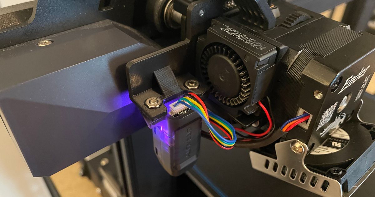
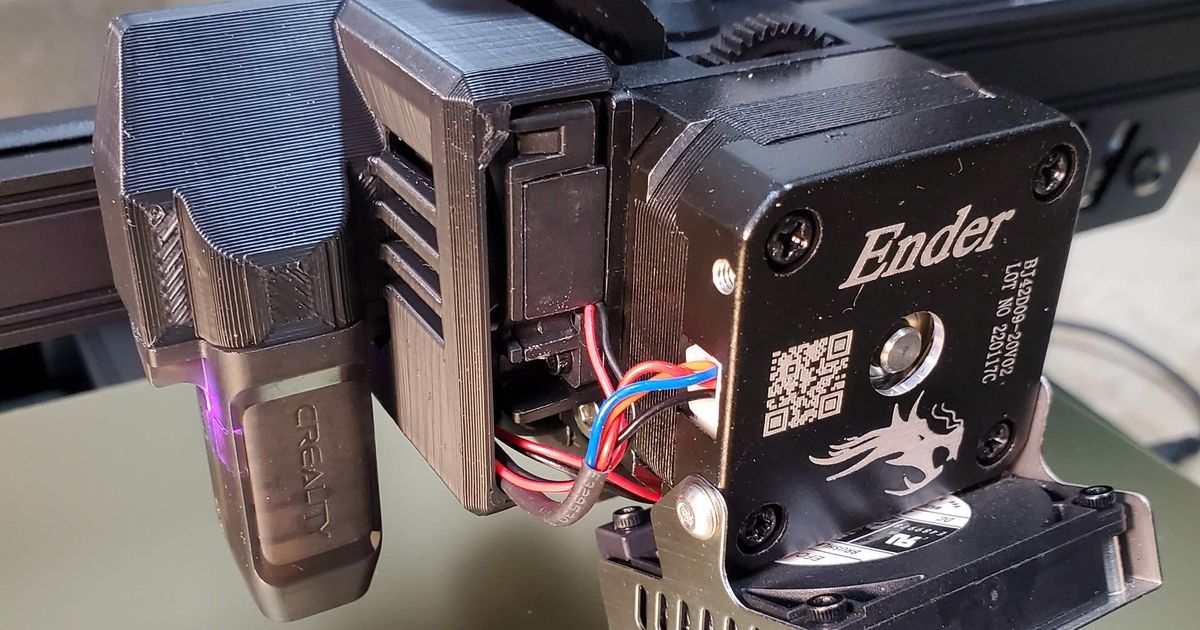
This part
Remixed to make it lighter (not that this is a limiting factor on a bed slinger, I just enjoy the technical challenge and aesthetic).
Also added a bit of material lower down to direct the heat sink fan air through the cooling fins, as well as lower the x offset slightly.
I kept most of the fan shroud to stop my fingers getting into the fan but kept a part of it uncovered to make lint removal easier.
Shown on my Ender 3 S1 Pro, but should work with the S1 and other printers with the Sprite extruder.
Probe offset X -45.0mm, Y 0.0mm (you must update these onto your printer so that it knows where the probe is)
Please post a make if you add this to your printer, let's see it!
Also see https://www.printables.com/model/449608-sleek-sprite-extruder-ribbon-cable-strain-relief
and https://www.printables.com/model/424208-super-lightweight-bed-leveling-knobs-for-ender-3-a
Klipper Configuration
You don't need Klipper to make use of this bracket, but I do, and here are the relevant parts of my Klipper configuration for your reference. Compare them to yours, and if there are differences, consider implementing them into yours (especially if you get “Move out of range” errors).
[stepper_x]step_pin: PC2dir_pin: PB9enable_pin: !PC3rotation_distance: 40microsteps: 16endstop_pin: !PA5position_min: -8position_endstop: -8position_max: 250homing_speed: 120[stepper_y]step_pin: PB8dir_pin: PB7enable_pin: !PC3rotation_distance: 40microsteps: 16endstop_pin: !PA6position_min: -8position_endstop: -8position_max: 230homing_speed: 120[bltouch]sensor_pin: ^PC14 # signal check port ^stand for pull upcontrol_pin: PC13 # singal control portx_offset: -45.0 # the exact offset depends on how the bracket was aligned when screwed in, but don't worry about getting it super exacty_offset: 0#z_offset: 0 # z_offset configuration, set in save_config below, not herespeed: 20stow_on_each_sample = false # false for faster probingsamples: 1 # originally 1probe_with_touch_mode = true[safe_z_home]home_xy_position:155,110 # position x is middle of bed - "x-offset", position y is middle of bed - to home in the middle of the bedspeed: 200z_hop: 10z_hop_speed: 10[bed_mesh]speed: 150mesh_min: 0,0 # as the probe is left forward of the nozzle, probing 0,0 will be OKmesh_max: 205,220 # probe max in X is stepper X "position_max" minus the bltouch "X_offset", probe max in Y is the print area maxprobe_count: 12,12 # if you shimmed your build plate with bits of tape or paper, use a high density like 12x12fade_start: 1fade_end: 10fade_target: 0mesh_pps: 2, 2algorithm: bicubicbicubic_tension: 0.2And if you're in the config files, you should add this so you can use the “screws_tilt_calculate” command (the position values are for this bracket).
[screws_tilt_adjust]screw1: 66, 192screw2: 240, 192screw3: 240, 22screw4: 66, 22screw1_name: Back Leftscrew2_name: Back Rightscrew3_name: Front Rightscrew4_name: Front Leftspeed: 200horizontal_move_z: 5screw_thread: CW-M4[gcode_macro screw_tilt]gcode: G28 SCREWS_TILT_CALCULATE[gcode_macro update_mesh]gcode: G28 bed_mesh_calibrate G1 X0 Y0 Z10 F4200 save_configMarlin Configuration - Work in Progress
Send the following g-code to your printer using Pronterface and a USB cable. Alternatively, download the gcode file, open it, remove the “;”, save, and load it on your printer. More info on: https://marlinfw.org/docs/gcode/M851.html
M851 X-45 Y0