Booknook with an Over-Engineered Combination Lock


Print Profile(1)

Bill of Materials


Description
I designed and built this Alice in Wonderland (already in public domain) inspired book nook.
I'm proud to say the whole locking contraption (my original design) fits into less than 1.5 cm.
Boost Me (for free)
If you would like to support my work, please consider leaving a like or a boost!
Main Features
- Secret storage behind a combination lock (completely built into the door)
- Configurable lock code
- Built in light (with a translucent front panel)
- Multi colour, but no AMS required. (well separated plates by colour and function)
- A1 Mini compatible (barely, the box is 18 cm)
- Needs at least 2 magnets (for the lock), but - if attached with magnets - the front panel can be easily detached from the box, and used as decoration as well. (see on the pictures, I have attached to the fridge)
- Glue may be required (only to attach the nose).
Assembly Instructions
Step 1 - Minor design elements
First, attach the nose, the eye and the bowtie to the front panel. The eye and the bowtie should snugly fit the holes prepared, while the nose will likely need some glue on the back.
![IMG_5091.MOV [video-to-gif output image]](https://makerworld.bblmw.com/makerworld/model/DSM00000002222399/design/68614890-c65b-4a21-a892-7e98cbd286be.gif?x-oss-process=image/format,webp)
Step 2 - Lock mechanism
Assemble the locking mechanism as per the demonstration. Make sure the wheel order is correct (first the wheel with only inner holes, then the wheel with both inner and outer holes, and third, the wheel only with outer holes). Make sure the wheel orientation is correct, the cutout on the bottom should look to the right. The central pins should snap in with a click. The pins on the wheel can be set to any position, but first, I recommend the configuration I have in the demonstration, so the combination to open the lock is the same. Insert a magnet into the bolt, and place the bolt in it's place at the bottom of the lock.
![IMG_5095.MOV [optimize output image]](https://makerworld.bblmw.com/makerworld/model/DSM00000002222399/design/1f99d757-fcb3-4f4e-9d76-689eebd914ce.gif?x-oss-process=image/format,webp)
Step 3 - Watch face
Place the black insert into the white watch face, in a way that the small cutouts align on the top. Place the face onto the panel. Assemble the small pin with the watch dial, and press the dial into the lock, to finalize the mechanism.
Note: in the video, I had the third pin already attached to the dial of the clock. They are printed separately, and I forgot that in the recording. You can just push them together.
![IMG_5096.MOV [optimize output image]](https://makerworld.bblmw.com/makerworld/model/DSM00000002222399/design/3aafe45f-b7f2-46b6-a3bb-d7999ca5f645.gif?x-oss-process=image/format,webp)
Step 4 - Watch case
Place the ring around the watch, in a way that the small cutout aligns on the top, and the yellow pin can be inserted, to stabilize the lock frame.
In the original demonstration I forgot to add the coat of the rabbit, do it after placing the ring, but before inserting the top pin.
![IMG_5097.MOV [optimize output image]](https://makerworld.bblmw.com/makerworld/model/DSM00000002222399/design/7df1c19b-174b-49e5-b706-0e18818f275b.gif?x-oss-process=image/format,webp)
![IMG_5103.MOV [optimize output image]](https://makerworld.bblmw.com/makerworld/model/DSM00000002222399/design/b8cf1072-c6a6-4d70-a199-88b0ef91e237.gif?x-oss-process=image/format,webp)
Step 5 - Frame bottom magnet
Insert a magnet into the bottom frame in a way that it repels the magnet in the bolt of the lock.
![IMG_5098.MOV [optimize output image]](https://makerworld.bblmw.com/makerworld/model/DSM00000002222399/design/0cecf83d-3d56-4f60-9821-64cd5b722a1b.gif?x-oss-process=image/format,webp)
Step 6 - Frame bottom/top
Assemble the bottom and the top parts of the frame. You can tell which ones are the bottom by looking at the cutout for the bolt of the lock. The grooves need to face as per the demonstration, as that's where the white panel will slide into.
Once assembled, both should be able to open freely on the hinge.
![IMG_5099.MOV [optimize output image]](https://makerworld.bblmw.com/makerworld/model/DSM00000002222399/design/fae7256a-40b6-4cd3-bbc2-61f9fb1acf05.gif?x-oss-process=image/format,webp)
Step 7 - Frame assembly
First, add the bottom of the frame to the white panel, then the left and right frame elements (the left has a slightly larger hole, to allow for the hinge).
Finally stabilize the frame by snapping in place the top part.
![IMG_5100.MOV [optimize output image]](https://makerworld.bblmw.com/makerworld/model/DSM00000002222399/design/16ad73f1-46dd-41e4-9901-a0bb632f221f.gif?x-oss-process=image/format,webp)
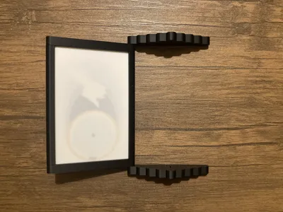
Step 8 - Attaching to the box
Optionally, you can insert the standard bambulab led into the box, for aesthetic reasons.
There are multiple magnet slots on both the box and the back of the front panel, so you can attach/detach them. If you are looking for more permanent fixture, feel free to glue them together in which case magnets are not necessary.
![IMG_5104.MOV [optimize output image]](https://makerworld.bblmw.com/makerworld/model/DSM00000002222399/design/03346667-db3f-4ca6-bda1-375b0c7d6d22.gif?x-oss-process=image/format,webp)
License
You shall not share, sub-license, sell, rent, host, transfer, or distribute in any way the digital or 3D printed versions of this object, nor any other derivative work of this object in its digital or physical format (including - but not limited to - remixes of this object, and hosting on other digital platforms). The objects may not be used without permission in any way whatsoever in which you charge money, or collect fees.
Comment & Rating (0)