10-19inch Drawer for Raspberry Pi 3+4+5 [V2]


Print Profile(4)


Bill of Materials


Description
What’s new in V2
- Improved Raspberry Pi 5 + OLED clearance (V1 was very tight with some OLED/display stacks).
- Dedicated RTC battery compartment: fits the official Raspberry Pi 5 RTC Battery and common RTC battery box / coin-cell holders (often with ON/OFF switch and replaceable coin cell).
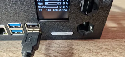
- Optional front SD card slot in the front panel (much easier OS swaps / backups).
- Supports two SD-adapter approaches (common generic/no-name parts from eBay/AliExpress):
- MicroSD (Pi) → Full-size SD (front) using a flat extension cable (recommended for a clean install)
- MicroSD (Pi) → MicroSD (front) using a flat extension cable plus a common MicroSD → SD adapter in the front slot
- Supports two SD-adapter approaches (common generic/no-name parts from eBay/AliExpress):
To be used with rack mounts:
- 10inch rack: https://makerworld.com/de/models/1142290
- 19inch rack: https://makerworld.com/de/models/1142528
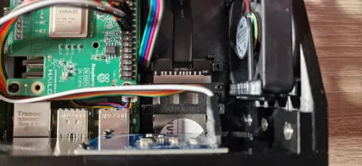
This drawer slot can mount a Raspberry Pi 3/4 or Raspberry Pi 5 and is designed for builds optionally using a Waveshare Micro HDMI adapter board, a MicroSD (TF) to SD-Card adapter and a 1.5” OLED display (SPI variant).
It also has enough space for up to two PWM modules, up to two 30x30x8mm fans (default Raspberry Pi fans, no screws needed) a step-down converter, different RTC battery models and several cable fasteners.
Note: Many SD extension cables/adapters are “China generic” with changing names. Search using the keywords below and compare the photos to the examples in this model.
Print files (4 main plates)
- Drawer (Main Plate) + Optional SD-Card fixation
- Raspberry Pi 3 Frontpanel (multiple variants, each as its own print plate)
- Raspberry Pi 4 Frontpanel (multiple variants, each as its own print plate)
- Raspberry Pi 5 Frontpanel (multiple variants, each as its own print plate)
The photos show: The Drawer (Main Plate) combined with Raspberry Pi 5 + HDMI + OLED + SD-Card Slot front panel. The HAT you may see is a AI HAT+, so HATs may fit depeding on nylon standoffs (M2.5 x 15 + 5 tested).
SD Card Slot: compatible adapter types (search keywords)
These are typical listings / keyword sets that work well for finding compatible parts:
- Type A (MicroSD → Full-size SD extension, UHS-I capable wording is common):
- “Micro SD UHS-I Card Extension Cable SDHC SDXC UHS-I Card TF Memory Card 15cm”
- Also try: “microSD to SD extension cable”, “TF to SD extension”, “FFC/FPC SD extender 10cm 15cm”
- Type B (MicroSD → MicroSD extension + standard MicroSD→SD adapter in the front):
- “Micro SD to TF Card Kit Male to Female Flat Flexible Extender 15cm”
- Plus a standard “microSD to SD adapter” (the common passive plastic adapter).
If your cheap sd card adapter/cable does not work (important note)
On some extenders there is an SMD resistor on the small PCB inside the SD-shaped end. In a few cases, removing that resistor has fixed Pi 4 boot issues for me. If you go that route: do it carefully, at your own risk, and expect the extender warranty to be void. I tested with Type B (resistor removal) and Type A. Both do fit, you only have to print the SD Card fixation from main plate (plate 2).
The UHS-I adapter worked out of the box since it was directly compatible with Raspberry Pi. If you like using MicroSD-Cards I used the adapter MicroSD to SD wich is mostly included with MicroSD-Cards because a MicroSD front panel itself would be to small and SD-Cards look pretty well.
RTC Battery Compartment (Raspberry Pi 5)
This drawer includes a battery bay for the Raspberry Pi 5 RTC backup power.
Fits the official solution
- Raspberry Pi official RTC Battery (ML2020, 2-pin JST plug)
(the official accessory is a small rechargeable pack with an adhesive pad)
Also fits common “China generic” battery boxes
- Many sellers offer an RTC Battery Box / RTC Battery Holder with an ON/OFF switch and a replaceable coin cell.
- Typical product dimensions (very common listing): 33.00 × 28.00 × 5.00 mm, cable length ~19 cm.
- These modules are usually designed for 2032-size cells (often sold as LIR2032 rechargeable; same physical size as CR2032).
Search keywords (no brand)
- “Raspberry Pi 5 RTC battery box ON/OFF switch JST-SH 1.0 2pin”
- “RTC battery holder for Raspberry Pi 5 LIR2032 33x28x5 19cm cable”
- “Pi 5 RTC coin cell holder CR2032 / LIR2032 JST 2pin”
Hardware / additional components used
I have used the following additional components:
- Screws (M2.5, pointed) for Raspberry Pi and HDMI board mount (found none in bill of materials)
- M3 nuts and screws for mounting base plate with front plate (listed bill of materials)
- Optional: Nylon standoff for Raspberry Pi board: 2.5x15+5 if you like using HATs like AI HAT
Optional Parts (depending on front plate you use):
- 128x128 1.5” OLED display (SPI)
- Waveshare Micro HDMI adapter board for Raspberry Pi 4+5
- SD card fixation: 4x M2x4 mm screws (metal)
- 2x FAN 30x30x8mm
- 2x PWM Mosfet Trigger Board (15A 400W)
- DC-DC Converter Modul 30W (step-down module with USB port)
- 1x PCA9685 (16-channel I²C PWM driver board)
- RTC
- RTC option A (official): Raspberry Pi RTC Battery (ML2020, 2-pin JST plug
- RTC option B (generic): RTC Battery Box / Holder (LIR2032 / CR2032 size, often with ON/OFF switch, replaceable coin cell), approx. 33×28×5 mm, ~19 cm cable
Wiring reference (optional fan/PWM setup)
- Power
- 12V DC jack -> DC-DC step-down.
- Step-down USB output powers the Raspberry Pi.
- Step-down 5V output (pads/terminal, not USB) -> MOSFET trigger board Power IN.
- Fans (5V)
- Fan + -> 5V from step-down.
- Fan - -> MOSFET board output (low-side PWM switching).
- PWM control
- Raspberry Pi -> PCA9685 via I²C (SDA/SCL + 3.3V/VCC + GND).
- PCA9685 PWM channel -> MOSFET trigger board signal input.
- PCA9685 GND -> MOSFET trigger board GND.
Important
- All grounds must be common (Pi/PCA9685 ↔ step-down ↔ MOSFET ↔ fans),
- otherwise PWM control may behave erratically.
Optional smoothing:
- Electrolytic capacitor across 5V and GND near the MOSFET/fan supply
(e.g., ~470–1000 µF) to reduce stutter at very low duty cycles.
Note:
- Currently only one MOSFET trigger board is populated/used, the second is optional.
Boost Me (for free)
If this model is useful to you, feel free to leave a Boost. Thanks for your support!
License
You shall not share, sub-license, sell, rent, host, transfer, or distribute in any way the digital or 3D printed versions of this object, nor any other derivative work of this object in its digital or physical format (including - but not limited to - remixes of this object, and hosting on other digital platforms). The objects may not be used without permission in any way whatsoever in which you charge money, or collect fees.
Comment & Rating (2)