
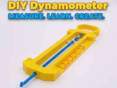
DIY Dynamometer (Educational & Functional)
Print Profile(1)

Description
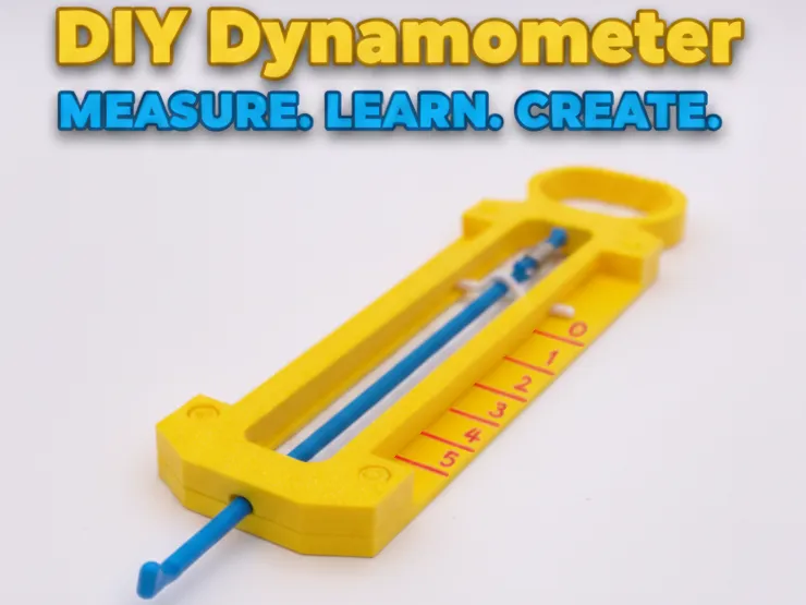
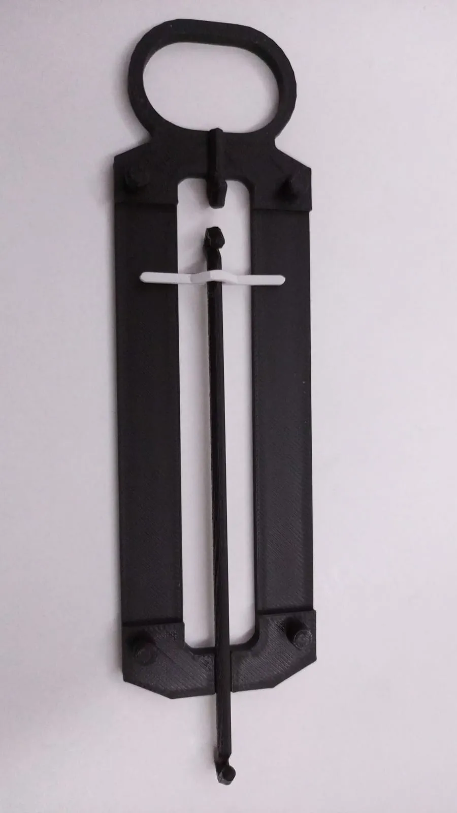
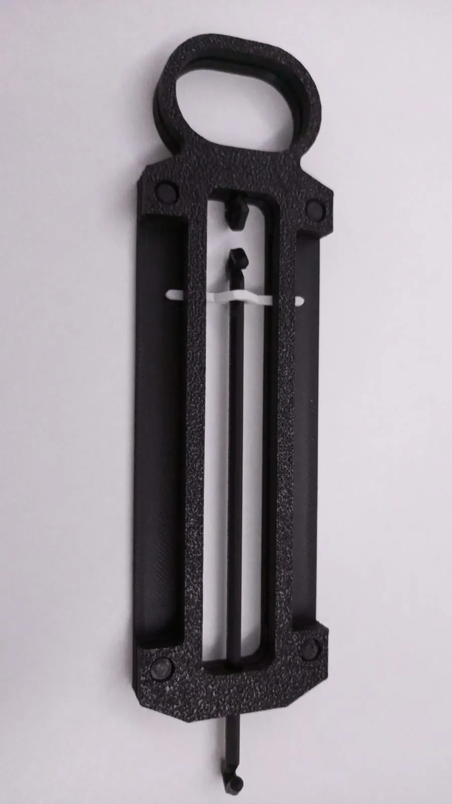
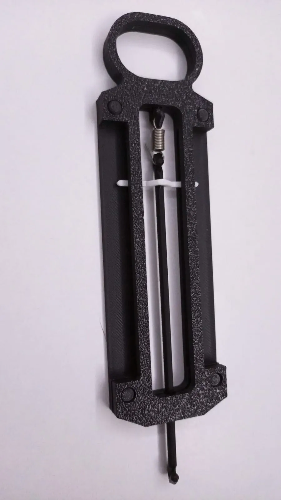
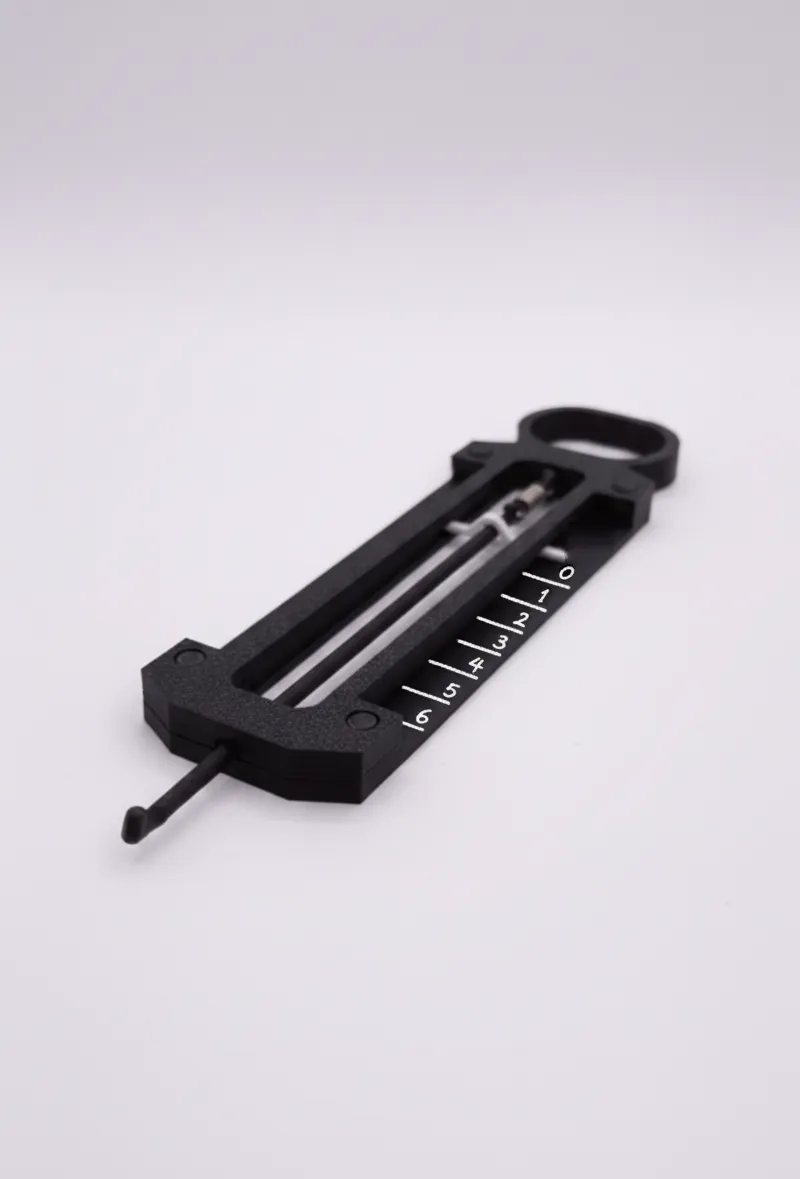
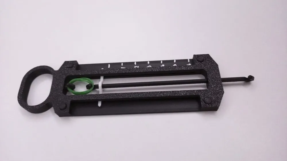
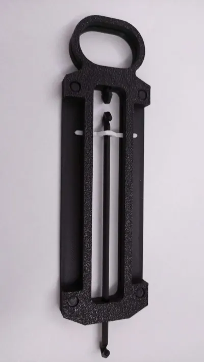
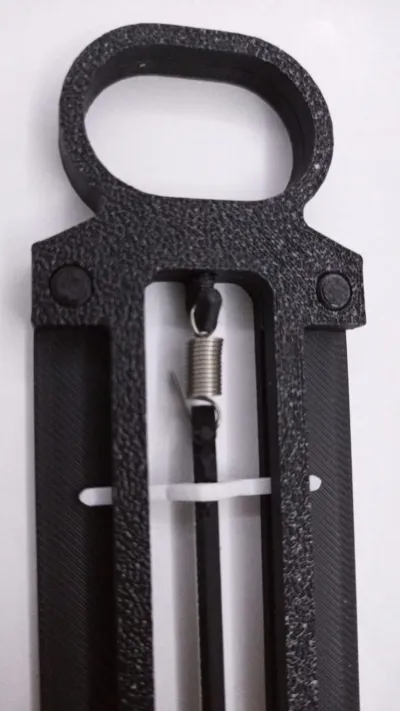
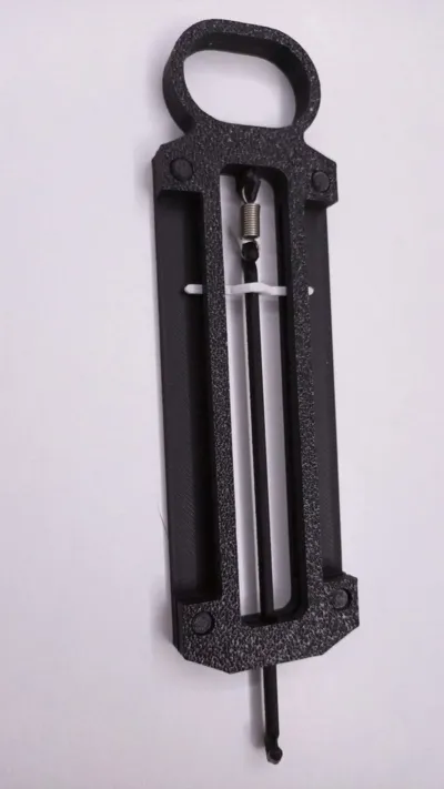
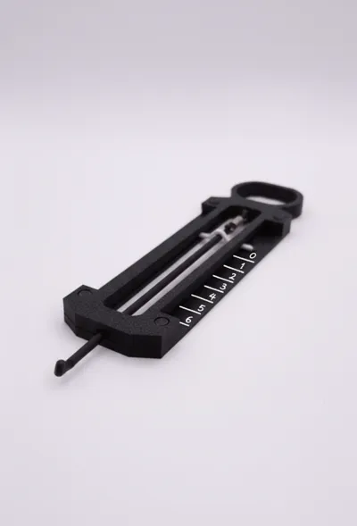
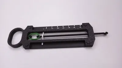
Are you looking for a fun and educational project to explore the principles of force and measurement? This 3D printable dynamometer is perfect for students, educators, and makers alike! Designed for simplicity and functionality, it allows you to easily measure forces using a common metal spring or a rubber band.
Key Features:
- Educational Tool: Great for physics experiments, demonstrating Hooke's Law, and understanding force measurement.
- Easy to Print: Designed with 3D printing in mind, the parts are optimized for FDM printers using standard PLA filament.
- Simple Assembly: Requires minimal additional components (just a metal spring!) and can be put together quickly.
- Robust Design: The interlocking parts ensure a sturdy and reliable instrument once assembled.
- Customizable: Easily adaptable for different spring strengths to measure various force ranges.
What you'll need:
- 3D Printer: (e.g., Ender 3, Prusa i3, Bambu Lab P1P/X1C)
- Filament: PLA recommended for ease of printing and good strength. (White PLA used in examples for clear visibility).
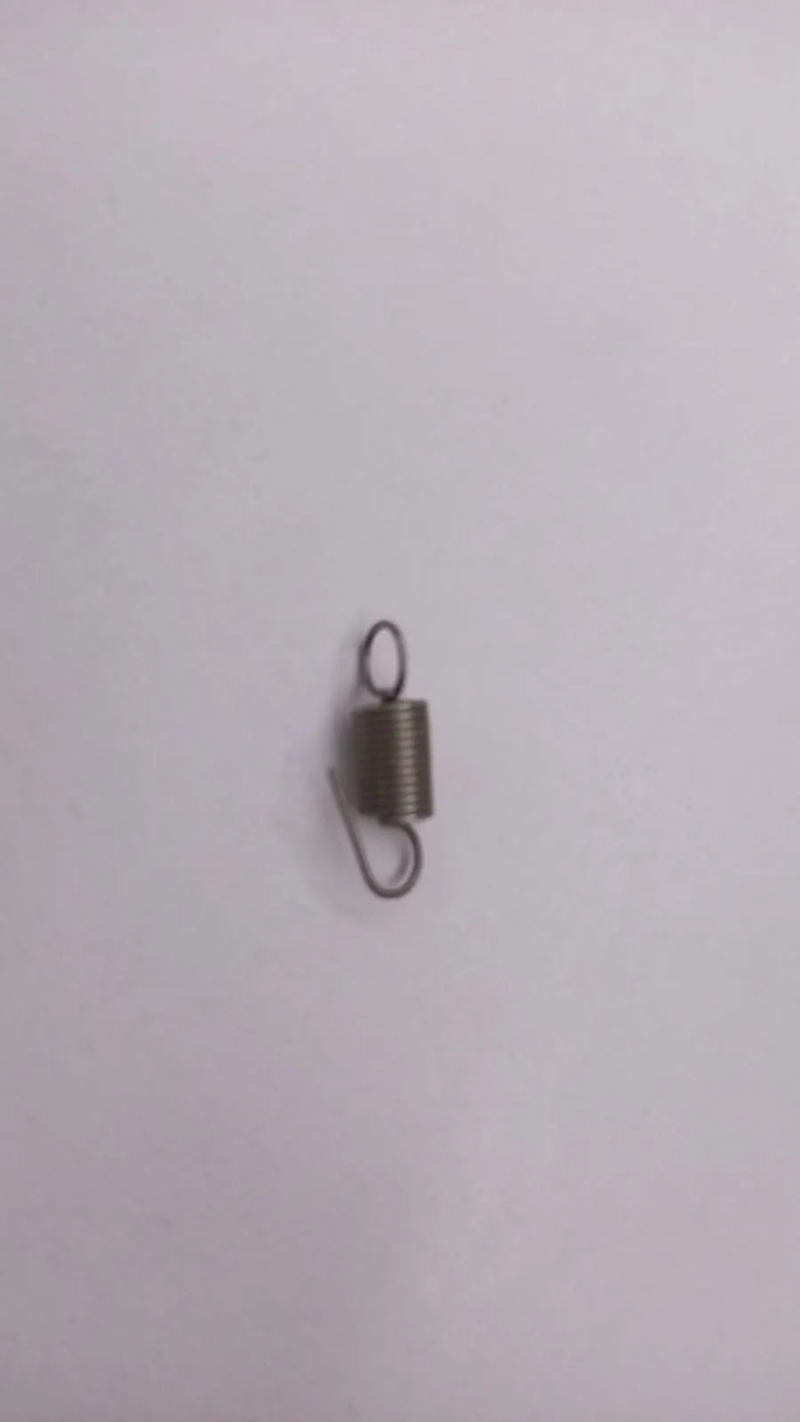
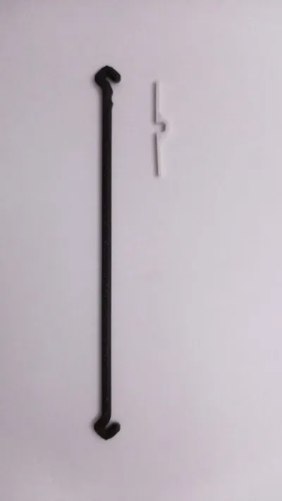
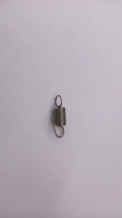
- Metal Spring: (A common extension spring with hooks on both ends will work best. The exact dimensions will depend on the force range you want to measure.)
- (Optional: Super glue for permanent assembly, though friction fit might be sufficient for some parts).
Assembly Instructions:
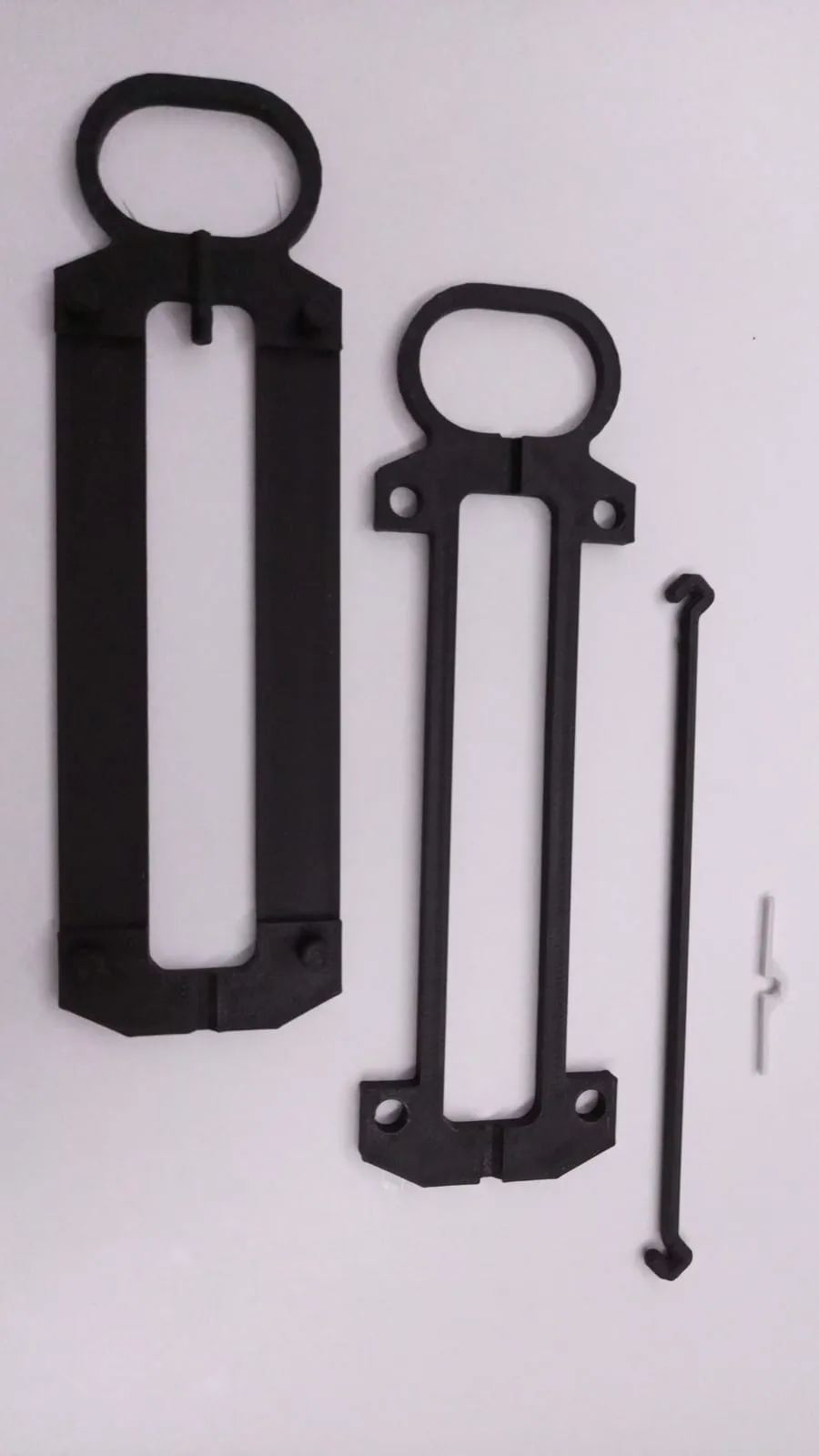
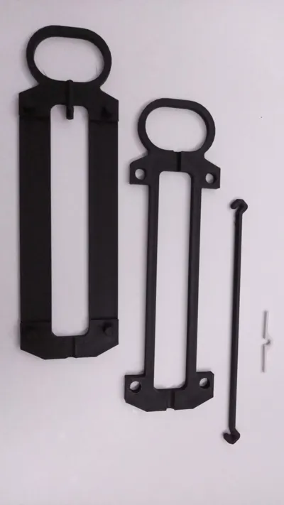
- Print all .stl files provided. Ensure good bed adhesion and appropriate print settings for your printer and filament.
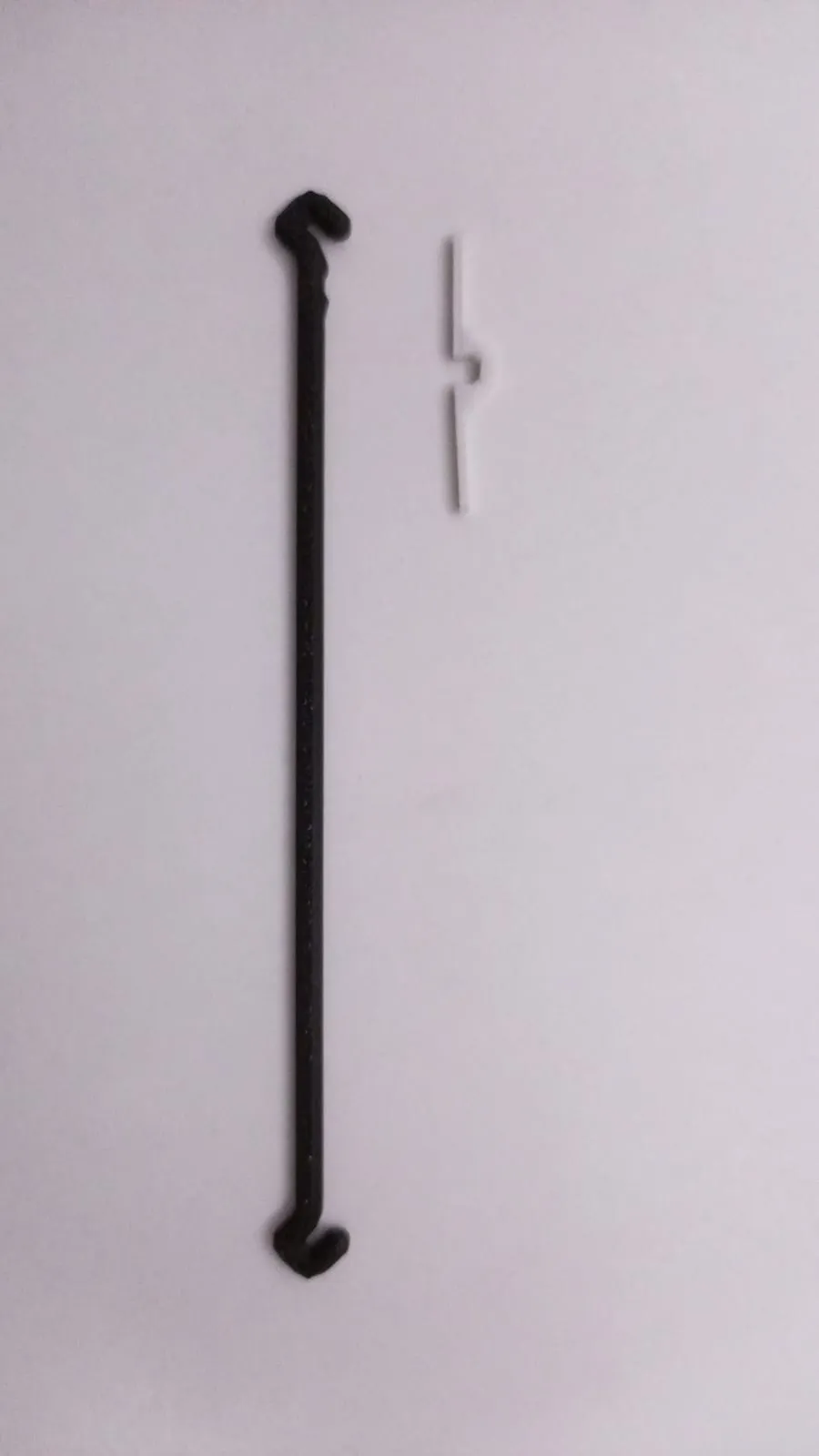
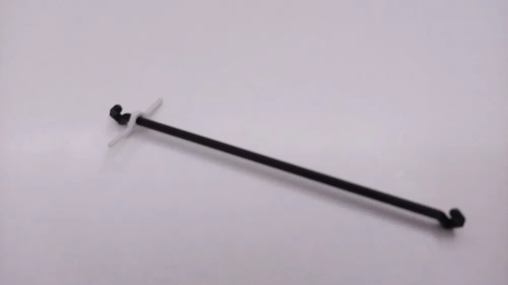
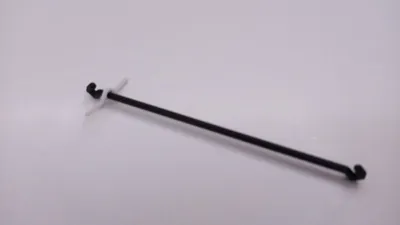
- Insert the needle into the drawbar's groove and push until it securely locks into place.
- Position the drawbar within the main frame/body's groove, ensuring the needle side faces inward.
- Align the upper frame/body over the lower frame/body, carefully guiding the pins through their corresponding holes for assembly.
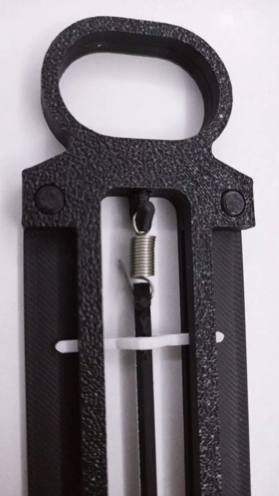
- Insert the metal spring between the two hooks of the inner sliding mechanism.
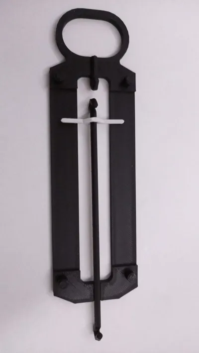
- Assemble the outer frames, ensuring the sliding mechanism with the spring is correctly positioned within the grooves.
- Secure the components together (refer to the exploded view for guidance).
- Calibrate your dynamometer using known weights to mark your scale!
Boost Me (for free)
If you enjoyed the model, a quick like & comment would make my day! Sharing is always appreciated, and if you feel like giving it a boost, that would mean the world to me – thank you so much!
Print Settings Recommendations:
- Layer Height: 0.2mm
- Infill: 15-20% (Gyroid recommended)
- Supports: Not needed, but check your slicer's preview.
This dynamometer is a fantastic way to bring practical physics into your workshop or classroom. Download the files and start printing today!
License

You may create derivative works based on this object, provided that all such derivative works are published exclusively on the MakerWorld platform and include proper attribution to the original creator. You may not share, upload, host, distribute, or publish this object—or any derivative work of this object—on any other digital platform, marketplace, or distribution channel. Commercial use of this object and any derivative works is strictly prohibited. This includes, but is not limited to, selling, renting, sublicensing, or using the object in any context in which you receive monetary compensation or other financial benefits.


Comment & Rating (12)