
Pastamatic - Motor Upgrade


Print Profile(2)


Description
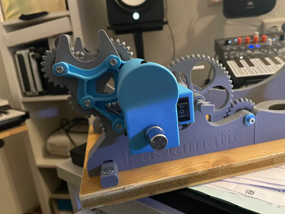
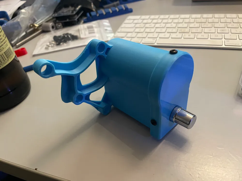
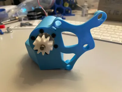
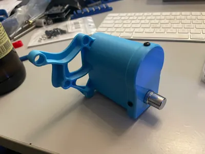
This is my Motormount for the great and fantastic Pastamatic.
Why this Motor mount?
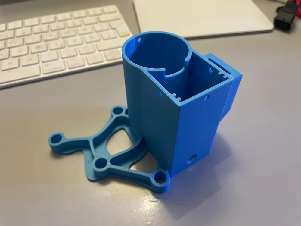
- easy to Print → Only took Control to the adaptive Layer by the Main-Housing itself. No Suports needed or other things like that
- Very stable also by using my screwable Pins.
- Needs less Space
- fast Print
- I took a lot of time and trails to get very good Dimensions
The following Parts are not Printable and u have to buy it. The linked items are from Amazon.de but u can find it on your “Local” Country spezific Amazon all over the World. Also u can find it at Aliexpress.
- Dc Socket: https://www.amazon.de/dp/B09PD6J4BN?psc=1&ref=ppx_yo2ov_dt_b_product_details
- Motor Driver: https://www.amazon.de/dp/B0B7G9GXMP?ref=ppx_yo2ov_dt_b_product_details&th=1
- Motor: https://www.amazon.de/dp/B071GTTSV3?ref=ppx_yo2ov_dt_b_product_details&th=1
- Power Supley: https://www.amazon.de/dp/B07L5GP7SD?psc=1&ref=ppx_yo2ov_dt_b_product_details
- 6Pcs M3x8 → Motor
- 4Pcs M3x5 → Housing
Also u can use my Pins to get a god and stable size on the Pastamatic.
Did you know my Guiding Cube Upgrade for the great Pastamatic?
Installation:
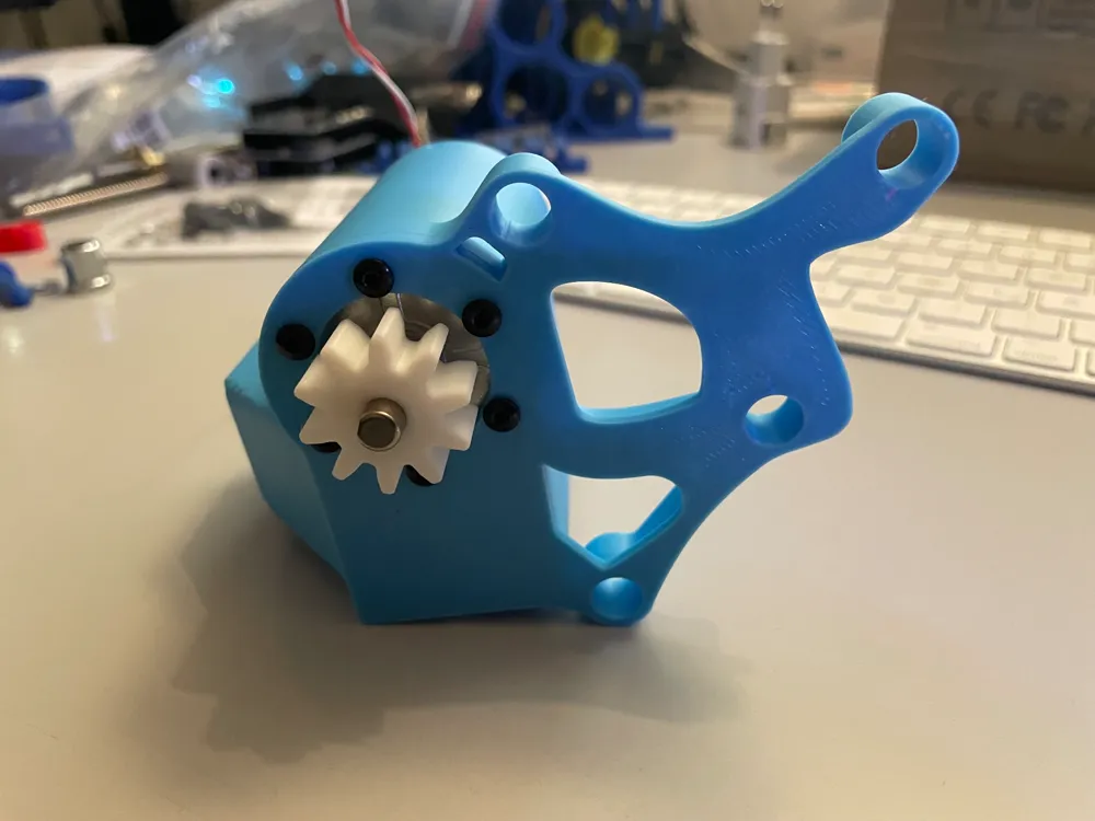
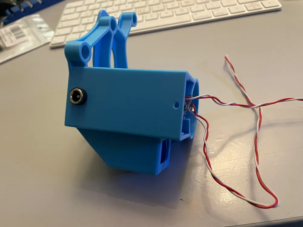
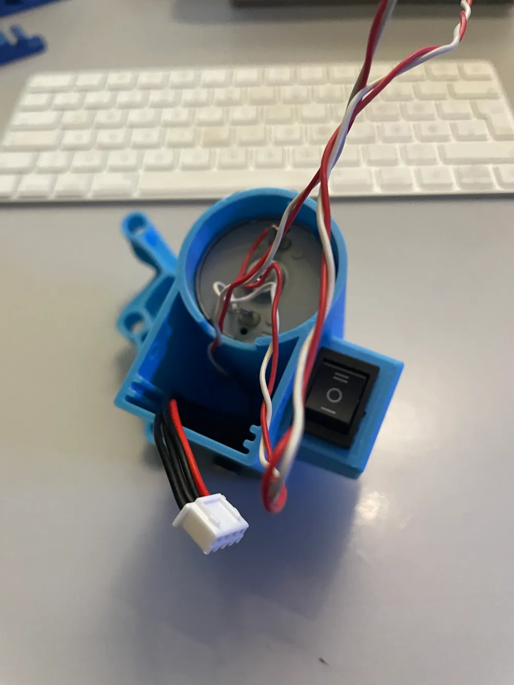
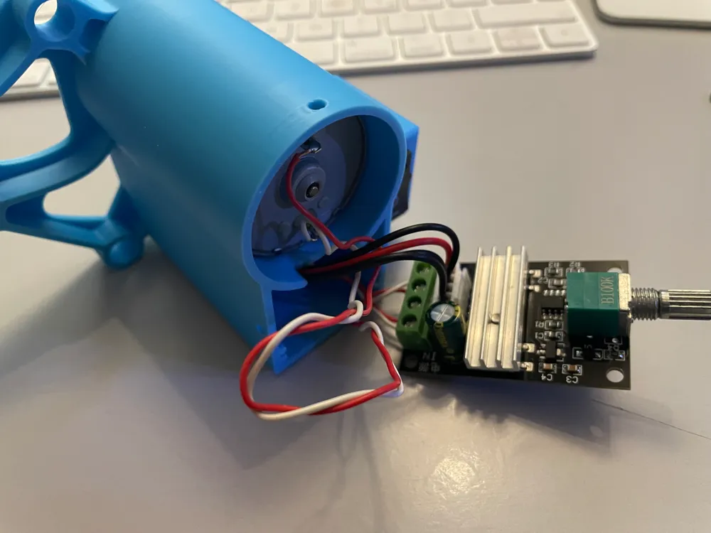
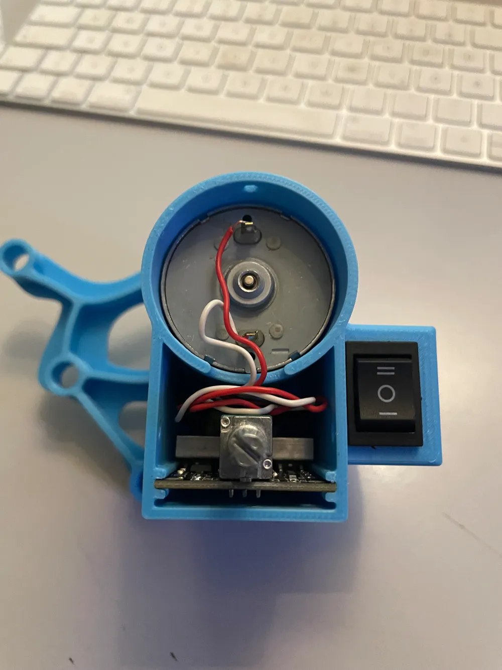
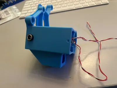
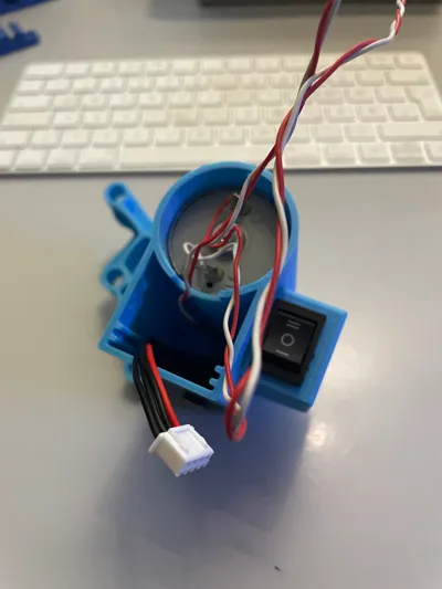
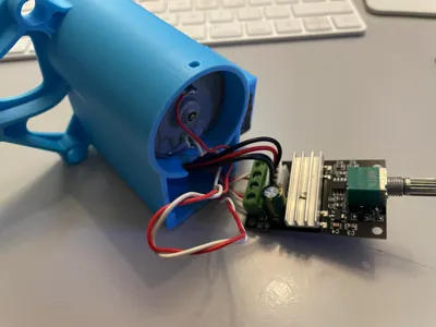
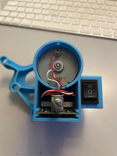
Please read this manual complettly bevore installing anything! If you watch the Pictures above, they are according to the following steps:
- The DC-Socket shoould be the first! U will hate me for the position. But it was the best way at all. If you are not a Magician or someone of people with equal abilities like a Magician you should soldering the Cables to the Socket first. The best legth is from the Socket hole to the Housingoutlet + 20mm or a Thumb. Someting like that. After you solderd the Cables and put the Socket in the hole you can screw it down. Otherwise, if you are an Magican or something like that, why you have to Print 3D?¿
- Install the Motor it self.
- Solder the Cables to the Motor → Instead you can do this before step #2. The cable has a good length when → it goes from the installed motor down the Elektronic housing and a little bit back again. → There is enough space in the Housing!
- Install the Switch and it's Cable.
- Now you can took all the Cables together on the little PCB.
- Took the PCB in its Place between the Guidinglips.
- Get the Housingcap on it and screw it smoothly…
- Now all is ready for Marriage with the Pastamatic…
Thats it!
Update:
14.March 2024: - Updated the Print Profile that could make issues on the Lid.
Enjoy, have Fun and Visit or Follow my Profile for more!
License

You shall not share, sub-license, sell, rent, host, transfer, or distribute in any way the digital or 3D printed versions of this object, nor any other derivative work of this object in its digital or physical format (including - but not limited to - remixes of this object, and hosting on other digital platforms). The objects may not be used without permission in any way whatsoever in which you charge money, or collect fees.


Comment & Rating (150)