Hexagon LED Light (Large)


Print Profile(5)


Description
UPDATE: I've completed the successor to this light- and it's better in every way! Boosts are great and all, but please go download the new system, you'll have a way better experience and go from printed parts to finished light in way, way less time.
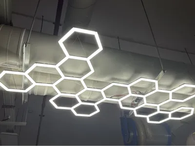
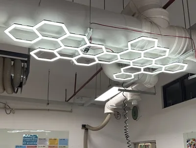
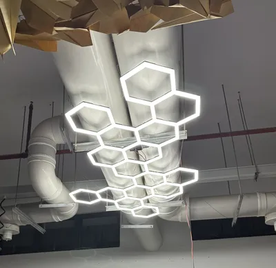
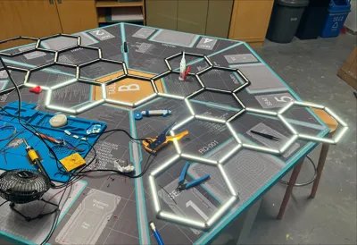
I designed this big hexagon light to help brighten up my workshop/classroom in a cooler way than just buying more panels. I've designed tons of things but until now I haven't posted any- apologies in advance but this is not as simple as ‘print and pop together’.
That said, this is a pretty cool light fixture. I've uploaded all the files used for this and made a few changes prior to uploading to improve the rigidity and allow for printing on smaller machines.
I've shared every file I made for this as STEP files, and plated them for an X1C to aim for a smaller volume. I did have to alter the biggest piece for that, but it's still included in the diffusion covers STEP file. Enjoy!
Printers and filaments used:
- Main frame parts: Creality Ender 3 V3 Plus with PETG-CF
- Diffusion covers: Creality Hi with Transparent PETG
- Support frame parts: Creality Ender 3 V3 Plus with PLA Matte
- Largest hexagon diffusion covers: Creality Ender 3 V3 Plus with Transparent PETG
- Frame braces and cable covers: Bambulab X1C with PETG-CF
- LED Strip clips: Creality Hi with PETG
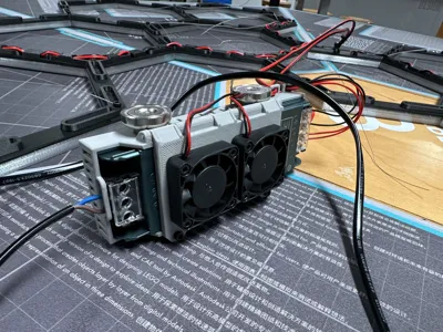
- *Power Supply Cage: BambuLab X1C with matte PETG
I used the Creality Hi for as many diffusion pieces as possible due to the surface finish of the resin-coated plate, and have found the quality of the prints excellent. I used a cold plate in the X1C when printing bracing pieces to get a flat surface on the bottom, but sliced it for an ‘engineering plate’ and used LAC glue. My 2 Ender 3 V3 Plus made layout easy, and enable me to print the biggest hexagon parts without needing to cut them. All prints on these machines were done on the reverse side of the textured PEI plate with glue, or a carbon-fiber pattern sheet. Without the extra space there's not a super clean way to cut the shape, but I hope that what I've done for smaller plates won't be too noticeable. If you have just 1 machine this will take a while to print.
*NOTE ABOUT POWER SUPPLY CAGE: I designed this for a specific power supply, and while it might fit other similar 150W/12.5A units, it will not fit other PSU's. I have like a range of others on hand, it does not fit anything else, though it could be made to work for a smaller one. The STEP file is included as an example, and can be modified by you if you wish- or just remade. I left out details here because it's really too specific. (I used magnets to mount it, a filament hinge, and 12V fans to keep it cool- may add a fan controller later)
Supplies and Tools Needed
- LED strips (I used 10 meters of 10 mm 2835 12V 240 LED/meter)
- Soldering Iron and Solder
- Wire (Or clip-on LED strip connections)
- A power supply (I used a 150w 12.5A LED unit)
- Quality Adhesive (I used Juju 9406 and was very pleased)
- 5mm or 6mm x 6mm M4 Heated threaded inserts
- 6mm M4 screws (for hanging)
- Wire for hanging (I used picture wire that I braided with a drill)
Instructions
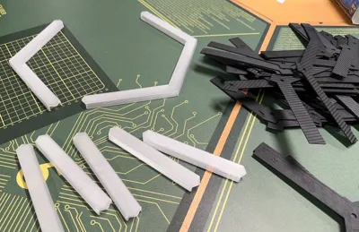
- Print main frame and support frame parts.
- Use flat print plates if at all possible to provide a smooth surface for adhesive. (If you want a texture on the face of the diffusion pieces go for it).
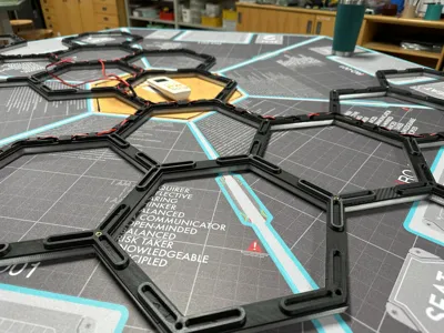
- Lay out the main frame and support frame to match the file (See reference PDFs or open full STEP file)
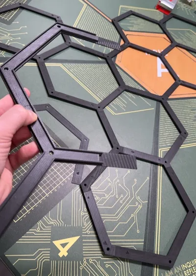
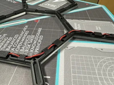
- Glue main frame components to support frame components in chunks, moving slowly and checking alignment.
- This ‘sandwich’ method was chosen to avoid supports, and because I knew that a big light would need more than just ‘snap together’ construction to hold up.
- If frame is strong enough, skip the braces, but if it feels less strong than you want, print those and glue in place.
- Cut LED's to ideal size. I chose the 240 LED/meter strips for tons of light but also because the cut points were closer than strips I had on hand. This meant minimal ‘unlit’ portions.
- Pre-solder the contact points on the strips to make wiring easier.
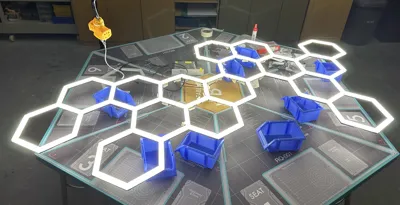
- Affix LED light strips in place with adhesive backing and the LED clips. Print a bunch of these, and press between the actual LED's across the strip.
- Map out how to split your power delivery.
- I connected everything in a line, like a dingus, before realizing how much power my strips needed and how much was lost- and needed to redo a ton of work.
- In the end I have 4 ‘power injection’ points roughly centered in 4 disconnected chunks of LED strip mesh. I'm not an electrician, these are not the terms they'd use, probably.
- After fixing my mistake, power never travels further than 8 strips from where it enters the system, resulting in even lighting with minimal voltage loss.
- It's easier to explain if the power coming from the power supply: 12V PSU → 2 power outputs → each output splits to deliver power to ¼ of the light → power is injected in the middle of the strips and has minimal travel to the ends.
- Step 6 took ages.
- Test everything, ensure even power delivery, etc. Run wires through included joint holes.
- Secure cables on reverse side using cable hider components as needed.
- Install heated inserts in joint holes where you want to add wires for hanging. (Be really careful that you don't push into wires. This won't happen with the correct size.
- Install diffusion parts. I glued them in place for structural benefit, but a wall mounted light may be fine without glue, or minimal glue.
- Use M4 screws to affix wire to the frame.
- Get help to attach to a ceiling, or spend a few hours struggling by yourself. Alternatively, place on a wall.
- Connect all wires to your power supply, brainstorm adding a switch later, and plug it in to bask in the illumination.
I'll share a video with more assembly details when I build the next smaller version.
I'm going to modify the design to create smaller versions for other parts of the room, as well as a wall-mounted RGB version, so stay tuned!
Comment & Rating (143)