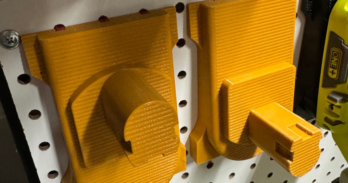
Ryobi 18v One+ AC Wall Adapter
Ryobi 18v One+ AC Wall Adapter


Print Profile(1)

Description
Do you have a Ryobi Power tool that would be better used with an external power supply, such as the bug zapper or one of the smaller non-hybrid fans? This will give you continual power to those tools using either a wall wart/adapter or power brick. I have used this print with both of the power adapters I have linked but you will only need to buy one of them. Of the two I prefer the wall wart (2.5A max) but it depends on your preferences.
NOTE: I have not found a power adapter which can provide enough power to run the grinder, belt sander, etc. so be mindful this will not run high-powered items!
Additional Items Needed:
* 2 X Power Jacks (5.5 x 2.1 MM): https://www.amazon.com/dp/B08F26JJKM
* 2 X Nickel Plated Leaf Spring Battery Connectors: https://www.amazon.com/dp/B06VTPWM6M
* Choice of the following:
* Universal AC Power Adapter (20v up to 2.5A): https://www.amazon.com/dp/B086JLYBQ7
* Universal AC Power Adapter (20v up to 6.0A): https://www.amazon.com/dp/B0CBK1D77J
* 3 X M3 Socket Cap screws: https://www.amazon.com/dp/B0CGHWWGCT (can be between 6mm to16mm in length)
If you are in a non-US based location then simply provide a power supply that outputs 20 volts with at least 1.5 amps of power. The higher the amperage the more tools you can power with this adapter.
Tools Required:
* Soldering iron.
* Solder.
* Long handled tweezers or similar tool.
* Allen wrench or similar for M3 screws.
Printer: Bambu Labs X1 Carbon
Filament: PLA or PETG will work fine.
Layer Height: 0.2mm
Wall Loops: 4
Top Layers: 4
Bottom Layers: 4
Sparse fill: 15%
Sparse pattern: gyroid
Main body can be printed without supports on some printers but results will be better if supports are used. Brims can be used for body and base but I do not recommended for the “clips” portion as it will cause issues with the 'spring' function.
Please see the attached PDF for detailed assembly instructions with photos.
Combination of two models:
https://www.printables.com/model/51711-ryobi-power-tool-pegboard-holders
https://www.printables.com/model/649222-battery-insert-compatible-with-ryobi-18v
Assembly Instructions:
1. Print the body, base, and clips, I recommend you use supports on the body and no brim on the clips.
2. Place the rubber dust cover boot into the hole where the power jack passes through the base.
3. Screw in the power jack, ensuring you line up the dust cover boot with the receiving tray in the base.
4. Place the lock washer and nut onto the backside of the power jack.
5. Tighten the nut until it is tight against the lock washer, do not over tighten or you can distort the dust cover washer.
6. Repeat the procedure to attach the power jack to the main body as well.
7. Twist the ends of the red wires and feed them into the nickel plated leaf spring battery connector. NOTE: This document assumes the center connector is the positive power lead which is red in color, be sure to confirm yours before proceeding!
8. Solder the two wires onto the battery connector, be careful the solder stays in the area with the wires and the solder doesn't flow behind the plate.
9. Using tweezers or similar, spread the nickle plated leaf spring connector slightly so it can slide onto the receiving part easier. Do not spread it too far or it might no longer hold or it can even break the connector.
10. Looking at the main body and at the top of the shaft you will find that one side is marked with a “+”, this is the 'positive' leaf spring connector side and we will be putting the red wire connector into this positive side. Again, the red is from the center of the power jack.
NOTE: Inside the opening of the shaft is a small trough/valley that will catch the bottom of the leaf spring connector, you will need to ensure the connector 'clicks' into this area.
11. Take the leaf spring connector and slide the long handled tweezers into it and then take this assembly and slide it into the main shaft inside the body.
12. Using a lot of force, push the connector onto the receiving part inside the main shaft, as you do so you should hear a 'click' as the leaf spring connector pushes into place. If you do not hear a click then examine the connector to ensure it is fully seated.
13. Repeat this procedure for the black wires.
14. Use the long tweezers to push the extra wires into the shaft of the main body.
15. Use 3 X M3 screws to attach the base plate.
16. Connect the battery adapter to your power tool, connect the power plug to the power connector and attach the power adapter to the wall, use the tool as recommended by Ryobi.
NOTE: When inserting the battery adapter if your leaf spring connectors push down into the body then you did not get them fully seated, use the long handled tweezers or similar in order to get the spring portion to 'click' into position.