Mechanical Arcade Pong. Atari Concept


Print Profile(1)

Bill of Materials


Description
Visit my latest creation, 100% customizable bracelets.

Membership
“Want to sell my designs? Get your commercial license here! ❤️ Join my exclusive memberships: 🔹 'Grateful' (3 USD): This membership is your way of saying "Keep creating!" with no extra benefits, just my eternal gratitude. 🔹 'Maker' / 'Marketer' (6 USD): Commercial license with mention. 🔹Maker free, (12USD) Free commercial license, no attribution.
Boost Me (for free)
I'm creating new and very interesting models, and your support motivates me to keep investing time and resources into new creations. If you can, I'd appreciate a free Boost to support my work. If you don't have a Boost, a "Like" or comment also helps a lot. Thanks for being part of MakerWorld and its creativity!
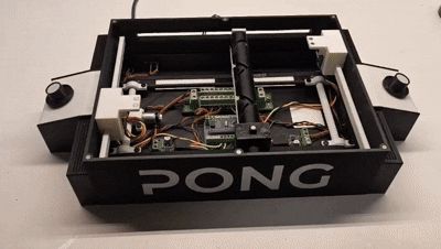
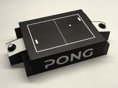
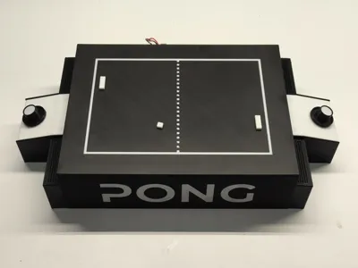
Mechanical Pong
Imagine playing the classic Pong game, but in the real world, on your table, with physical pieces moving before your eyes ⚙️ That's precisely what I've created! I present the Mechanical Pong project, a tangible and fully playable version of the legendary video game, elevated to another level through engineering and creativity
Now you can play and feel in your hands what previously only existed on a screen A unique experience for nostalgics, makers, and lovers of retro games 🎮✨
🕹️ I wanted to pay homage to this video game classic by bringing it into the physical world This idea was born from the inspiration I received from Maker World's arcade competition It sparked the idea, motivated me to develop this project Without this incredible initiative, I might not have been encouraged to design and build this creation Thank you for motivating the community with these creative ideas! I hope you enjoy the result as much as I enjoyed the process
🔹 Project Rationale and Target Audience
- Arcade Nostalgics seeking a tangible Pong experience
- Board Game Enthusiasts with a technological twist
- Collectors of unique replicas of classic video games
- Bridging the Digital and Physical: Combining the essence of the original Pong with the satisfaction of manual interaction
- Educational Project: Perfect for teaching mechanical and electronic concepts
- Decorative and Functional: An eye-catching object for any shelf
🔹 Functionality
- Concealed Mechanics: A mechanical system, hidden beneath the game platform, uses magnets to bring the movement of the ball and paddles to life
- Stop!: When you stop the ball, it's returned to the opponent
- Goal!: When you score a goal, the system pauses for 3 seconds before resuming
- Minimalist Electronics: Magnetic sensors, magnets, motors, and simple components provide tactile feedback to a classic
Assembly Instructions
Before you begin assembling the game, please note the following:
- VERY IMPORTANT Never connect the Arduino to the USB while it is powered with 7.5V
- It does not operate at 5V A standard USB will not work You will need to increase the voltage to 7.5V using a USB Speed Controller (IA002) This is because the motor control drivers operate at 6.5V, but don't worry, the motors will not operate at 7.5V (as they could burn out) they will operate at 5V as I have lowered the voltage with PWM in the Arduino programming
- No programming knowledge is required Simply copy and paste the code I've provided into your Arduino and make the connections as explained in the assembly guide
- This is a first model, an Alpha version of the project, so it may require some adjustments or updates, both to the parts and the model or programming There will be significant updates and other versions Any suggestions, improvements, updates, or faults appreciated will be well received in the comments
- Print in PETG or ABS for greater durability in moving parts, although it is also functional with PLA
- Ensure that all moving parts slide freely Sand or file all moving parts to ensure they are smooth and glide easily
- Grease the worm gear and sliding guides for better operation
- Make sure to place the magnets with the polarity detected by the sensors
- If the main motor spins in reverse, reverse the polarity It should start moving to the right
- In the electrical connection diagram, the + and - polarities are simply marked in red and black These connections are all joined to the power distributor
-------------------------------------------------
Updates and Improvements
25/07/2025:
- Some model parts have been updated in the profile After observing that on certain occasions the goal cam collided with the ball support without being detected, 3 magnets have been added to each side of the ball support instead of 2, thus expanding the detection range and preventing collisions
- The distance at which the magnets are positioned on the goal cam has also been reduced by 2mm
- It was previously 37.5mm, now it is 35.5mm
 |  |
 |
-------------------------------------------------
(At the end of the instructions you have the list of necessary materials Almost all materials are available in the official Bambu Lab store) Materials not available at Bambu Lab have an Amazon link in the assembly instructions themselves
Let's start with the base
Base Assembly Instructions Images Begin by removing all supports, but special mention should be made of this hidden cable gland support, through which we will need to pass the cables 
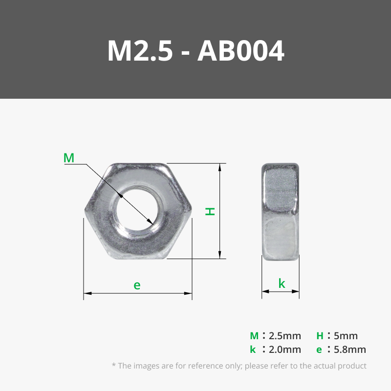
We need a total of 20 5mm nuts (AB004) that we have to fit into the game base (10 on each side) 
Then we insert the MR128 (EA004) 8x12x3.5 bearings inside the pulleys We need 14 units in total Depending on your printer and calibration, you may need to heat the bearing or pulley to 120 degrees to insert it
There are 4 toothed pulleys, 2 smooth pulleys and another 2 toothed pulleys with an elongated shaft But for now we will only use the 4 toothed pulleys


Then you need to take 8 of the small bushes and insert a 2.5x10 screw (B-AA005) 
That screw holds the toothed pulley to the shaft, allowing completely free rotation
You insert the pulleys into the shafts, the bushes into the pulleys, and tighten
Then, use 2 2.5x10 screws (AA005) for each bearing support You need 8 units for this step (but watch out, you'll need more)


Then screw the gear rack onto the side of the base using another 2 B-AA005 screws 
A list of electronic materials on Amazon
Now you can place the electronics You need 2 DRV8871 H-bridge controllers
IMPORTANT This sensor comes with straight connectors You will need L-shaped connectors (or bend them and then solder directly to the connector)
2 units DRV8871 controller module 1.5 A 2-channel H bridge DC gear motor controller board compatible with 3D printer Arduino 3.6 A PWM control module, integrated protection function: Amazon.es: Industrial & Scientific
- And here are the 90-degree connectors
Male and Female Connector Header, 2.54 mm Single Row Straight Pin Headers PCB, 40 Pins Breakaway PCB Soldering for Arduino Prototype Shield, 45 Pieces, 3 Types: Amazon.es: Industrial & Scientific
A power distributor
- An extension board for Arduino Nano
Binghe Nano Expansion Board 2 Pieces Nano IO Shield Adapter Nano IO Shield V1.O Expansion Board Compatible with Arduino: Amazon.es: Computers & Accessories
4 KY-003 Hall effect magnetic sensors
IMPORTANT
The code for programming the Arduino is in the design's documents
You don't have to touch anything, just copy and paste the code into your Arduino, connect the cables as explained in the electrical diagram and that's it!!
No programming knowledge is necessary


To place the KY-003 magnetic sensors you need to solder some 2x3.5x4mm insert nuts (AB009)
Something important to keep in mind is that the sensors come flat, and we need to bend them into an L shape so that they are above the connector, although then we will have to adjust them and find the correct position we need, but for a first assembly I recommend mounting them already bent


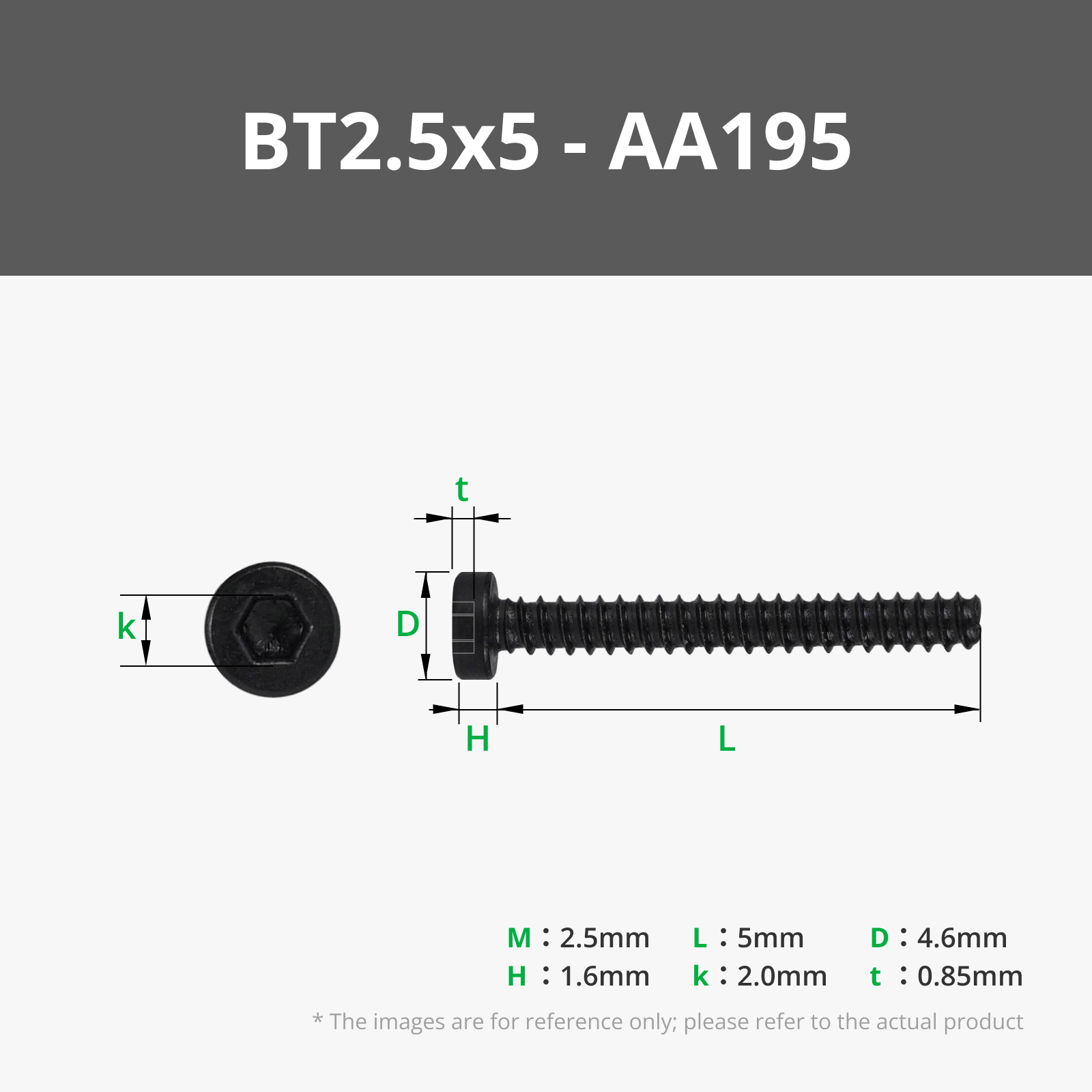
To secure the rest of the electronics we need some 2.5x5mm screws (AA195)
Or, in default you could also use some 2.6x8 (AA004) but cut to 5mm (with some cutting pliers they cut well)

In our Arduino Nano we need to cut these connectors where the red line is, because we are not going to use them, if we don't cut them they will impede the movement of the game 
Now take the USB-C connectors and the circuit breaker and insert them into their corresponding holes from the back 

Now on the shaft with the squares at the ends, insert 2 pulleys with the square hole And since this shaft is fixed, screw the pulley directly to the shaft with the 2.5x10 screws (B-AA005) 

Now place the shaft with the bearings on the bearings that are designed for the bearing to fit under pressure If it doesn't fit well, tap it, but the bearing must fit completely into its base 

Now take the 2 axles with the toothed drive pulleys, insert an MR128 (EA004) 8x12x3.5 bearing into each axle, and press fit into the motor shafts facing the D-shape on the shaft 

Once assembled, repeat the drive shaft securing process we did earlier Insert the bearings into their recesses and put on the caps 

Now we cut 2 2mm GT2 toothed belts with a length of 468mm or 234 teeth We connect them to the quick connector of the horizontal shaft bar that I have designed to make it easy to remove and put on Simply slide them on 

Pay close attention to how we cut the belt We must cut right at the end of the last tooth If we leave the space between teeth, it will not fit into the track, and we will not be able to insert the belt 

We take advantage and put the 4x2 magnet inside the cylinder (CA001) 
We now screw the linear shaft motor at 150RPM (LA002) to the L-shaped plate 
Now we screw the L-shaped plate to the horizontal guide with two 2.5x10 screws (B-AA005) We insert the motor through the horizontal hole, leaving the motor outside the box and the shaft inside 
We insert the other end of the guide into the track with a back and forth movement 
Since we already have the belt cut to size, we can release the drive shaft, insert the belt and tighten the shaft again You can also insert the belt directly into the guide coupling, that's up to each person to do better 
In the worm gear, we insert an MR128 (EA004) 8x12x3.5 bearing and then, inside the bearing we insert the gear This will be loose, as it must have free movement 

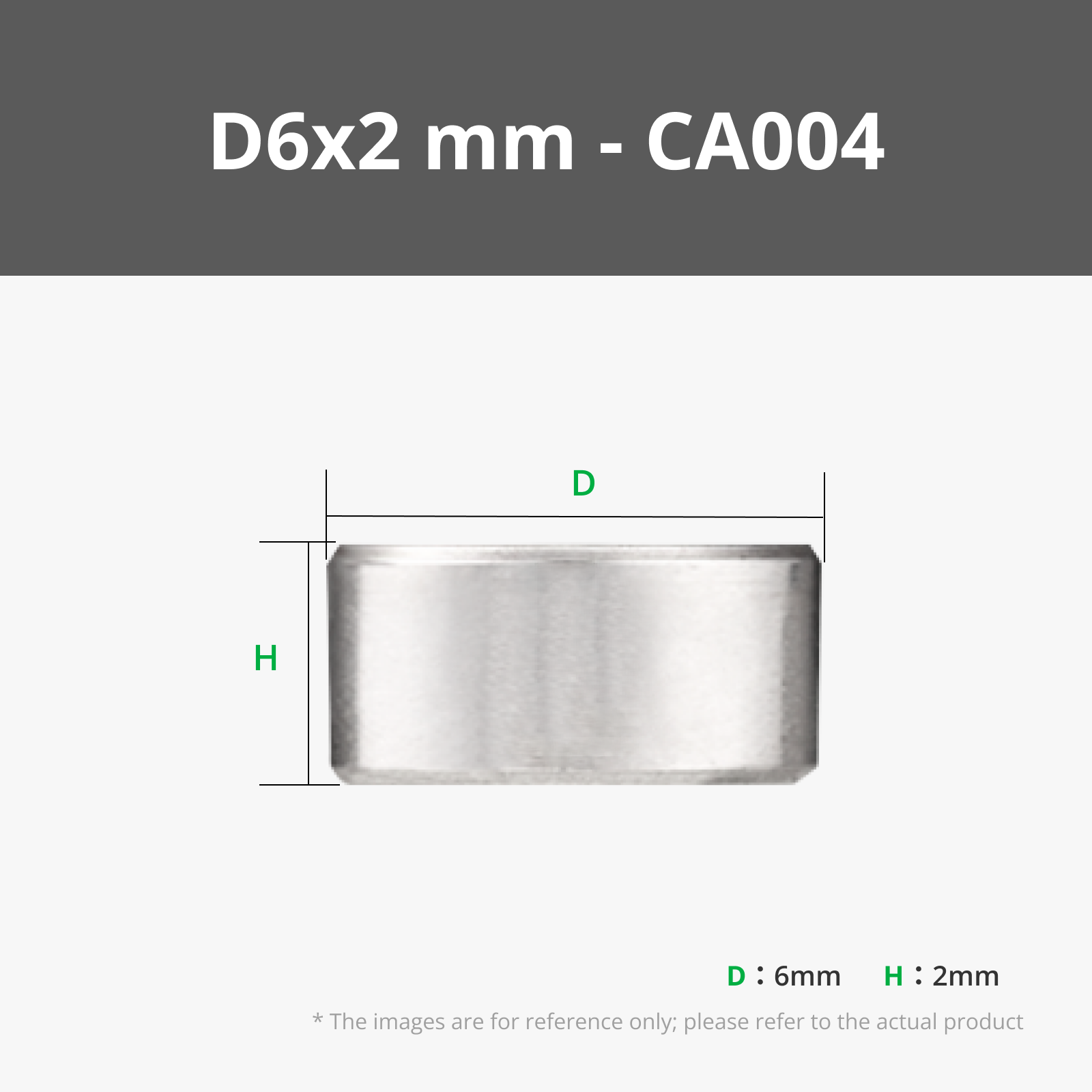
Now we glue the 4 magnets that the vertical shaft guide needs, two on each side These magnets are the ones that will make the sensors detect whether or not we hit the ball with the paddle
These magnets must be 6x2mm (CA004) and as before, it is vitally important to ensure the position in which we place them so that the sensors detect them
Important: After an improvement, there are now 3 magnets, not 2

Then we put the 4x2 magnet on the guide cover, which will be the one that moves the "Ball" here the polarity of the magnet doesn't matter, we will only have to take it into account when we put the other magnet on the ball 
Then we insert the Guide through which the worm gear will slide, and we insert the motor shaft inside the worm gear 

Once assembled, we place the rotating cam of the guide, and screw the lid with two 2.6x8 screws (AA004) 

We take the PONG letters and glue them into their corresponding holes 

And finally, in this section of the assembly, we put the 6 4x2 magnets that go on the top of the base box, and another 6 magnets on the lid, observe carefully how to put the magnets, because the polarity must be correct for them to attract each other 

Now we're going to assemble the control system
| We start by assembling the 2 control structures They only have 4 2.5x10 screws (AA005) and go in the holes I mark in the image Don't confuse them with the other small holes, those will be for putting on the caps | 
|
We solder 2 2x3.5x4mm insert nuts (AB009) in each of the paddle supports
And we glue or fit 2 4x2mm magnets into the holes at the top |
  |
We take the 2 bases where the controls will be mounted and put the 2 smooth pulleys, on which we previously mounted the bearings
Documentation (1)Assembly Guide (1)  LicenseIf you want to use this model commercially, please join my membership. Join Now This user content is licensed under a Standard Digital File License. You shall not share, sub-license, sell, rent, host, transfer, or distribute in any way the digital or 3D printed versions of this object, nor any other derivative work of this object in its digital or physical format (including - but not limited to - remixes of this object, and hosting on other digital platforms). The objects may not be used without permission in any way whatsoever in which you charge money, or collect fees. Related Models |
Comment & Rating (215)