
Infinity Space Box


Print Profile(1)

Description
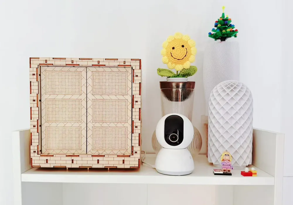
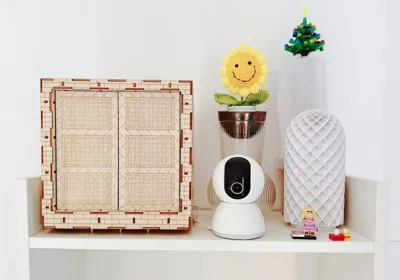
Infinity Space Box (Basswood)
Design Background
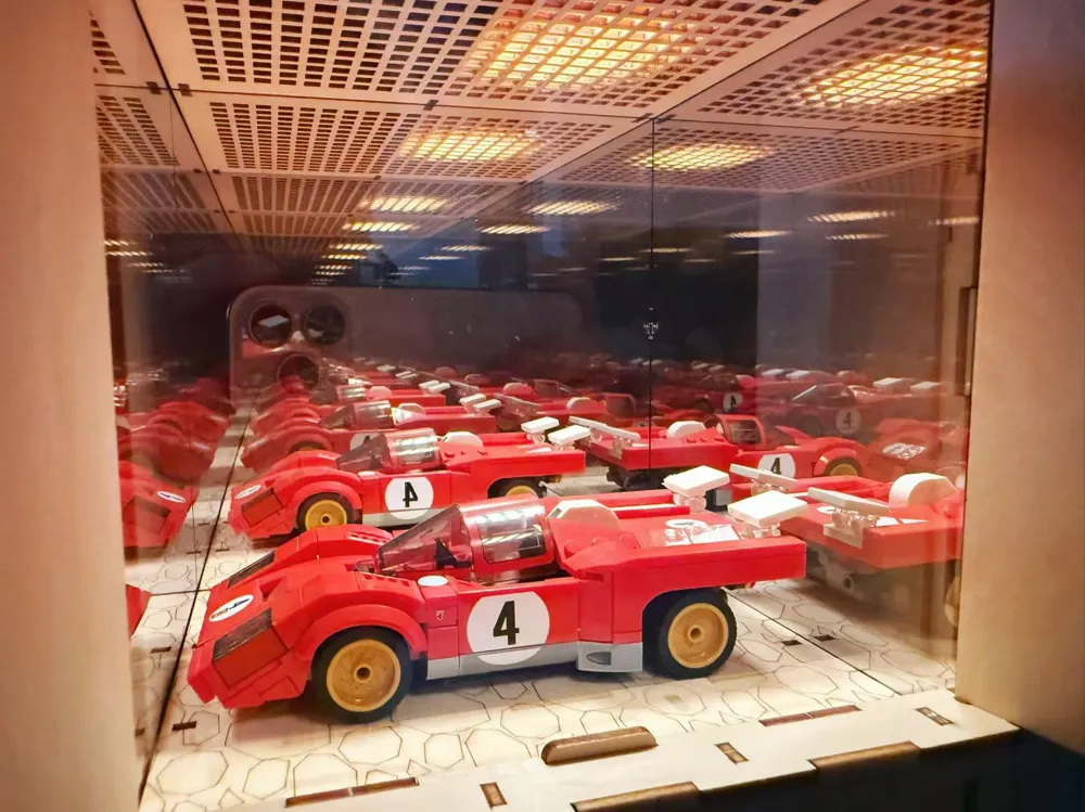
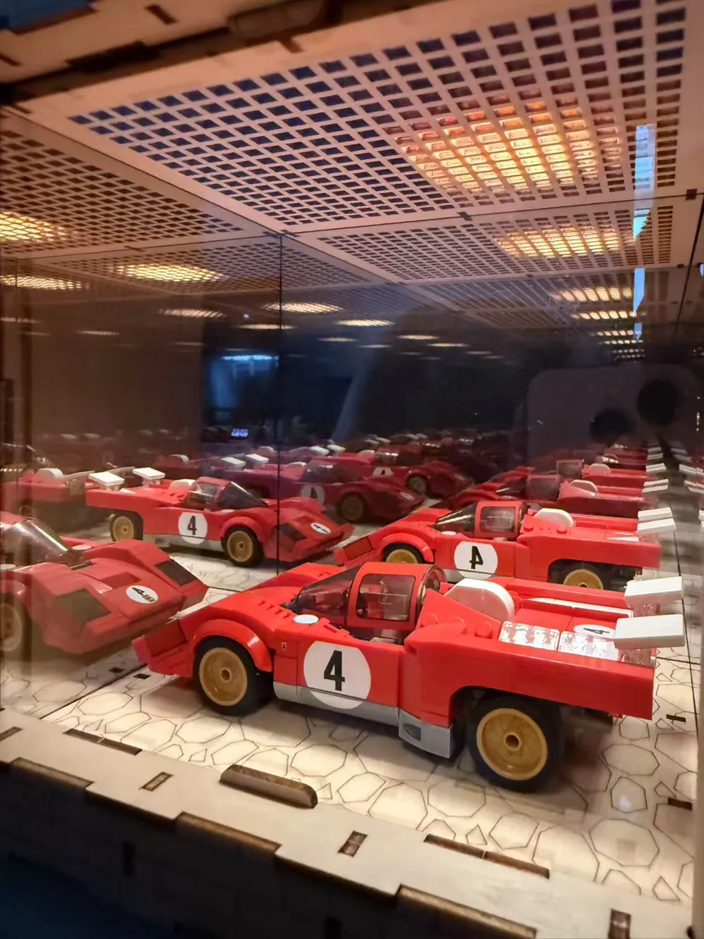
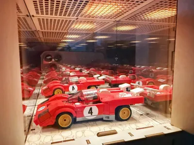
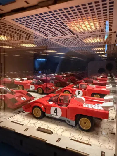
Providing a home for the “Ferrari.” I am enamored with the texture of wood, and I needed dust covers for some of my handmade creations while desiring a unique and engaging aesthetic, thus birthing this concept.
Initially, the purchased wood was actually 2.7mm, necessitating reinforcement with hot melt adhesive.
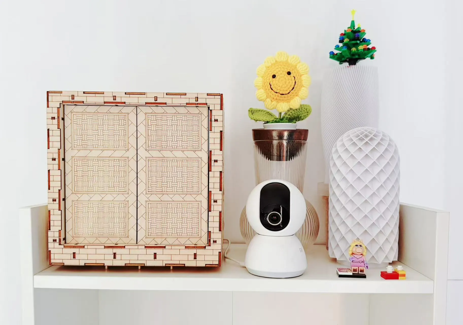
The interior accommodates models, maximizing both aesthetic appeal and storage capacity.
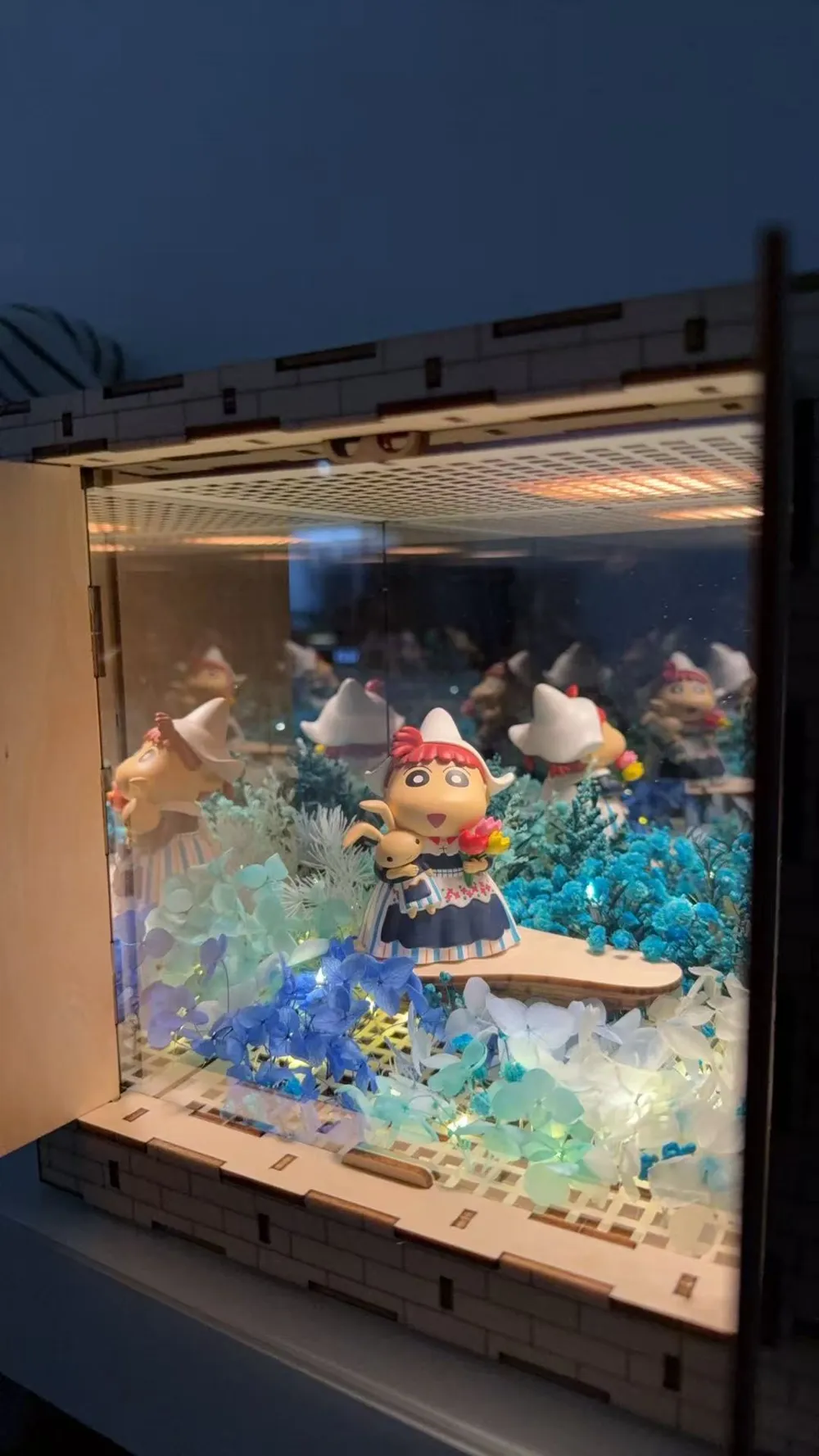
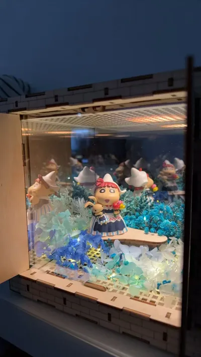
Below are two examples crafted by the author; internal items are all custom-made or commercially purchased.
Lego Garage:
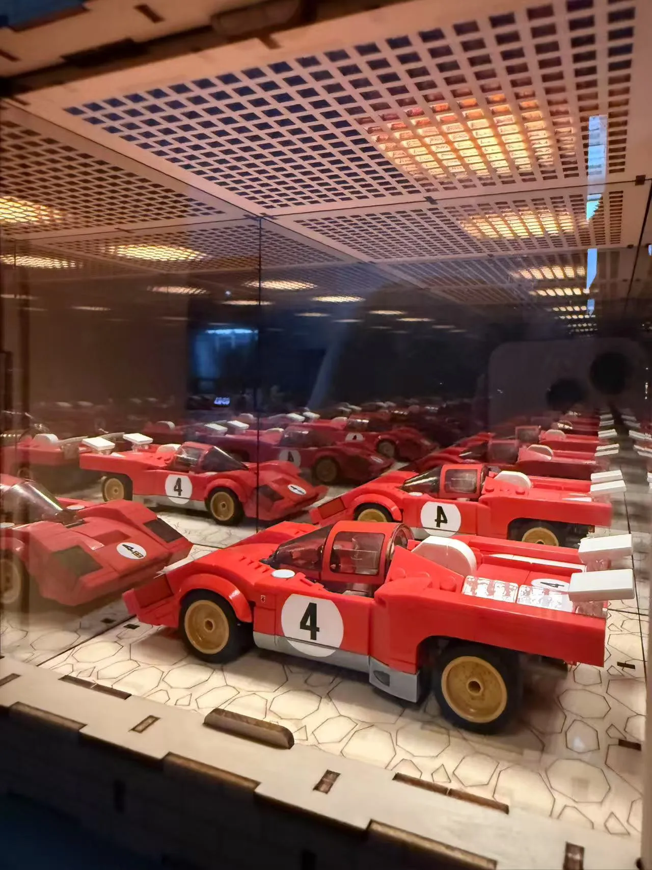
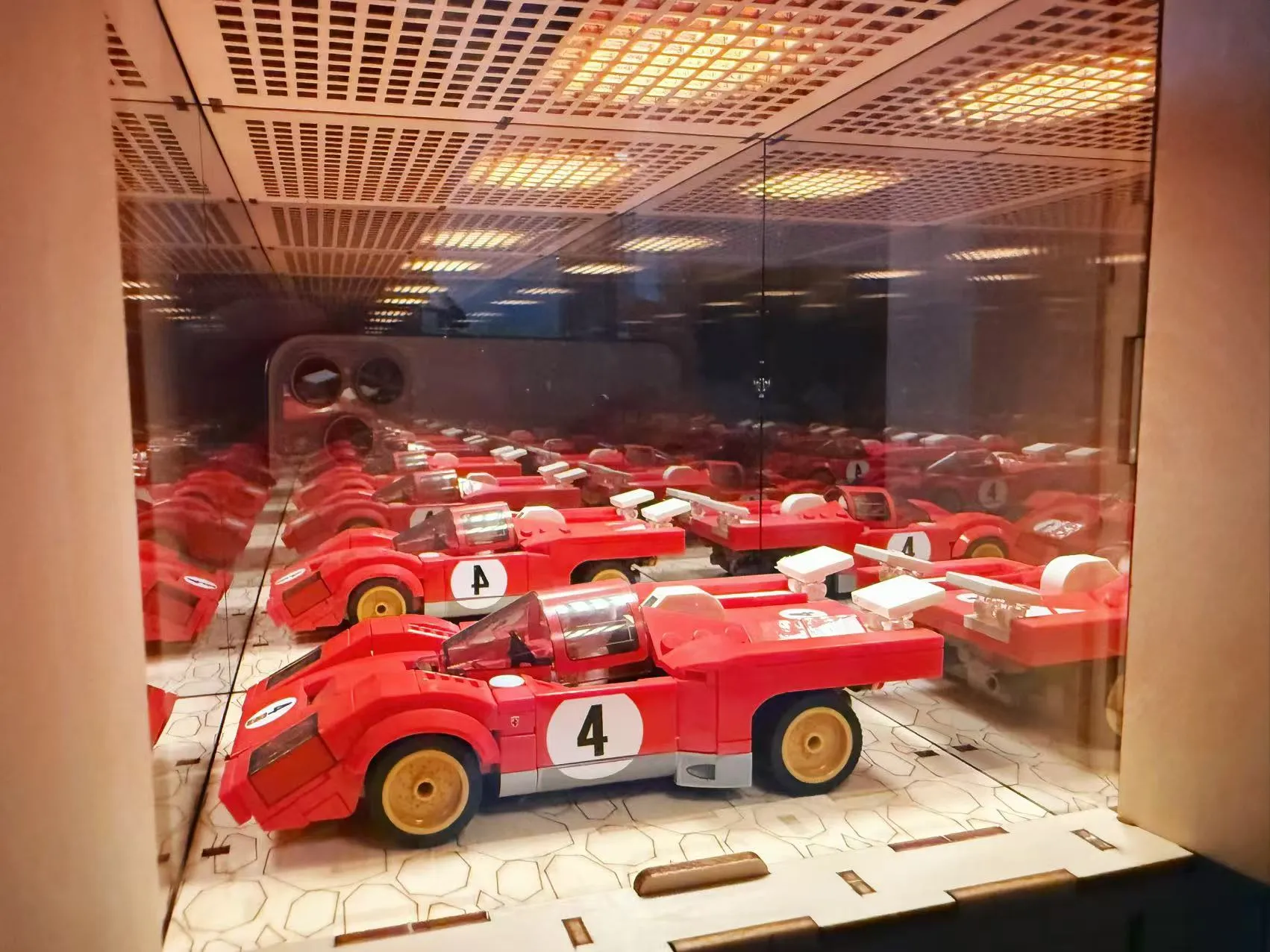
Infinite Flower Sea:
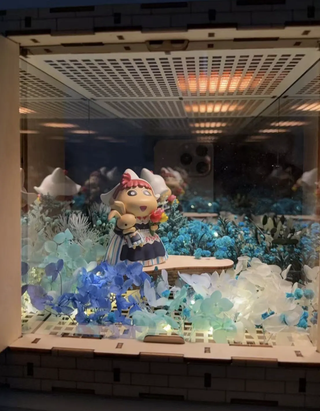
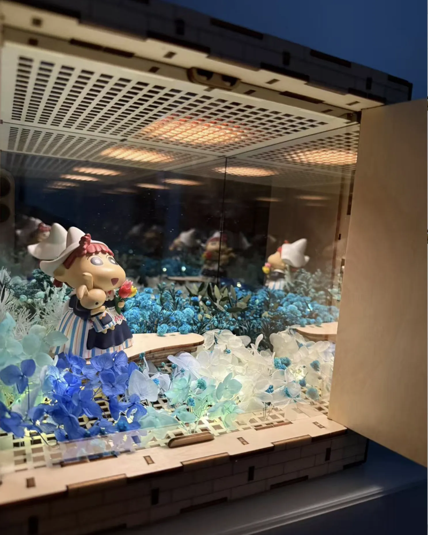
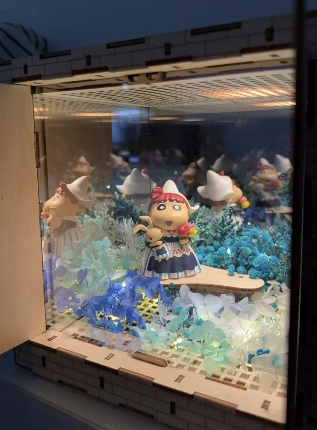
PS: A printable version of the box is also under development and undergoing print testing; it will be released subsequently; please stay tuned.
Box Specifications
Each component of the box incorporates a framework to reinforce the panels, enhancing durability and protecting the one-way and translucent mirrors. The provided lights serve as support and panel attachment points.
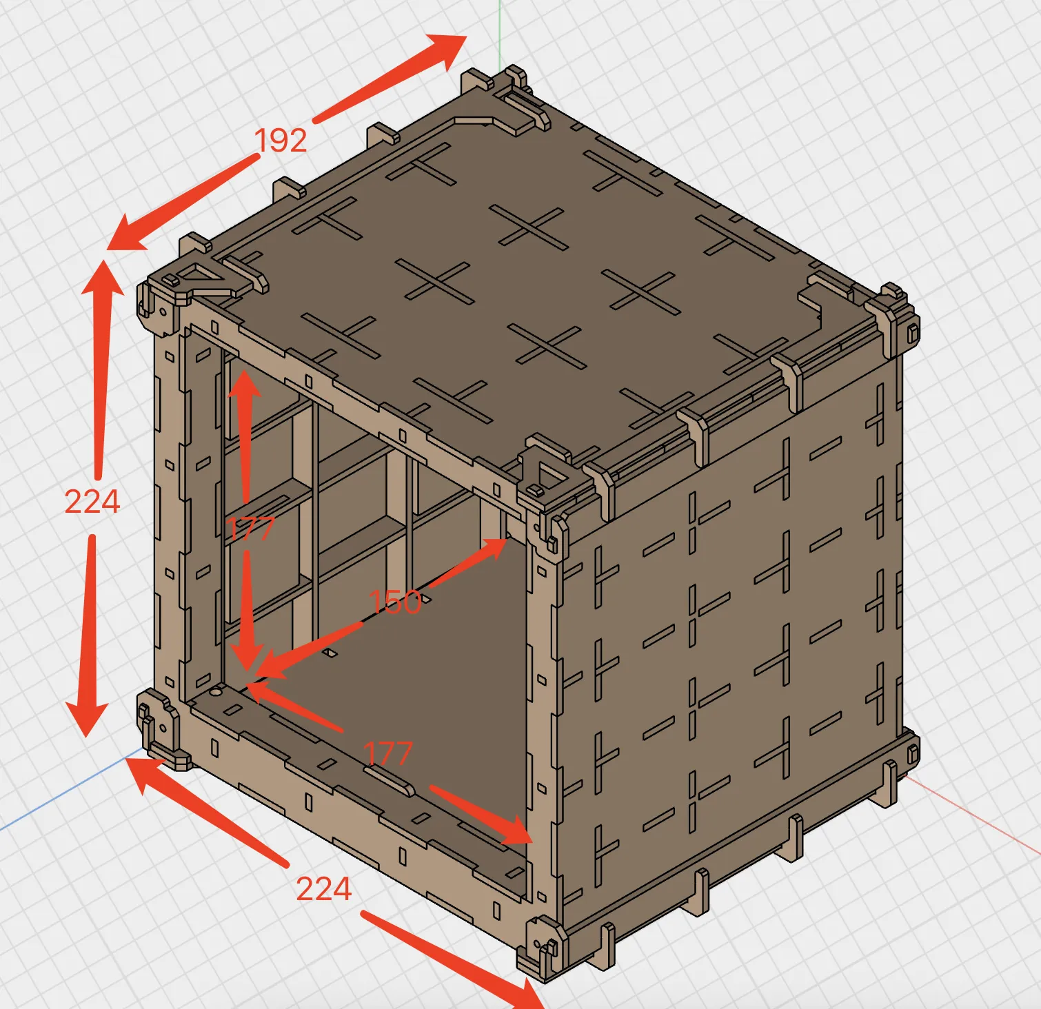
Dimensions:
- Exterior: 224W x 224H x 192D mm
Interior: 177W x 177H x 150D mm
Materials Required:
- Translucent Mirror: 150mm x 200mm, 1mm thickness, 2 pieces; 200mm x 200mm, 1mm thickness, 1 piece.
- One-way Mirror: 200mm x 200mm, 1mm thickness, 1 piece.
- Nano Adhesive:
- 2mm thickness, 20mm x 30mm width, 12 pieces (Purchasing a roll and cutting as needed is recommended; provides excellent protection and cushioning for the mirrors).
- 1mm thickness, 10mm x 50mm width, 8 pieces.
- TuZhu LED Light (MH001): 1 piece.
- Wooden Cotton Swabs: For use as dowels in the insertion holes.
- Magnets: 8mm diameter x 3mm width, 2 pieces (Optional; available in the TuZhu beginner kit; for door panel alignment).
- Small Metal Plates: Adhere to the door panels for magnet attraction. (Optional)
Diagram Explanation
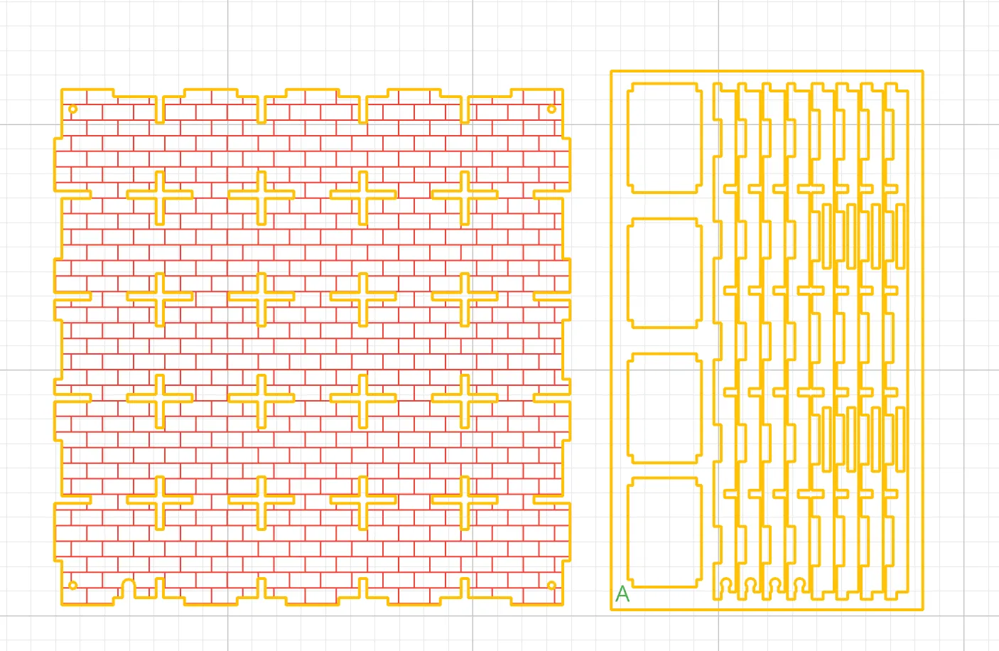
The author does not own a TuZhu H2D machine; a machine from another manufacturer was used. Adjustments have been made within the TuZhu software for optimal direct engraving, but additional clarifications are provided below:
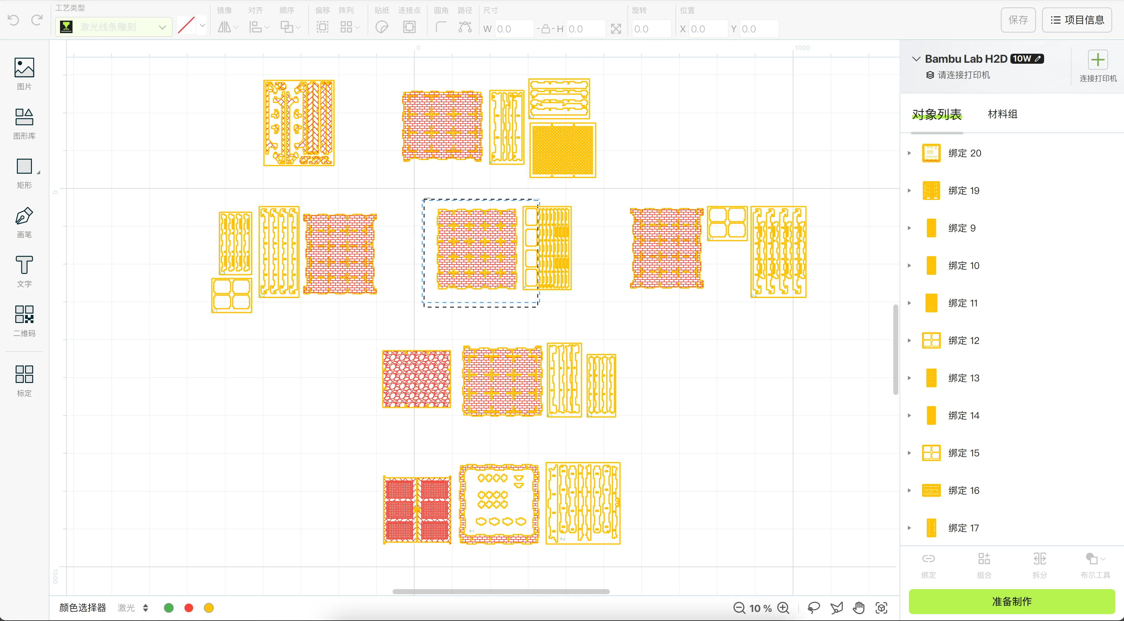
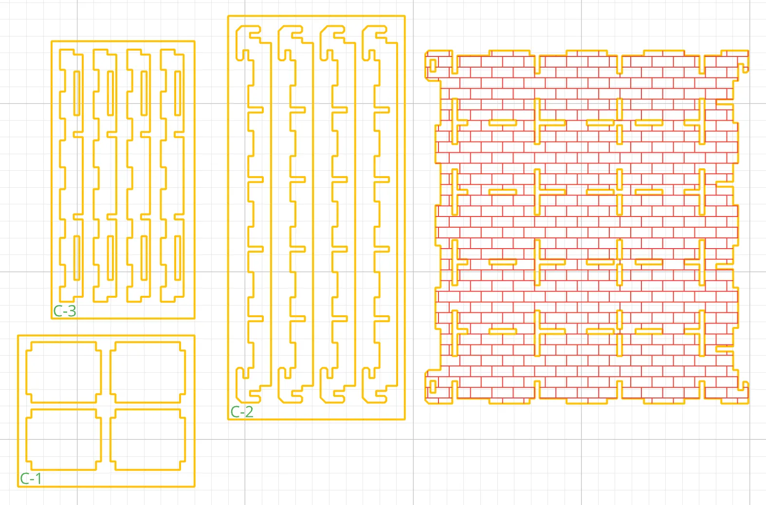
The diagrams employ three colors: yellow (cut), red (engraving), green (fill).
The processing order is green (fill) → red (engraving) → yellow (cut).
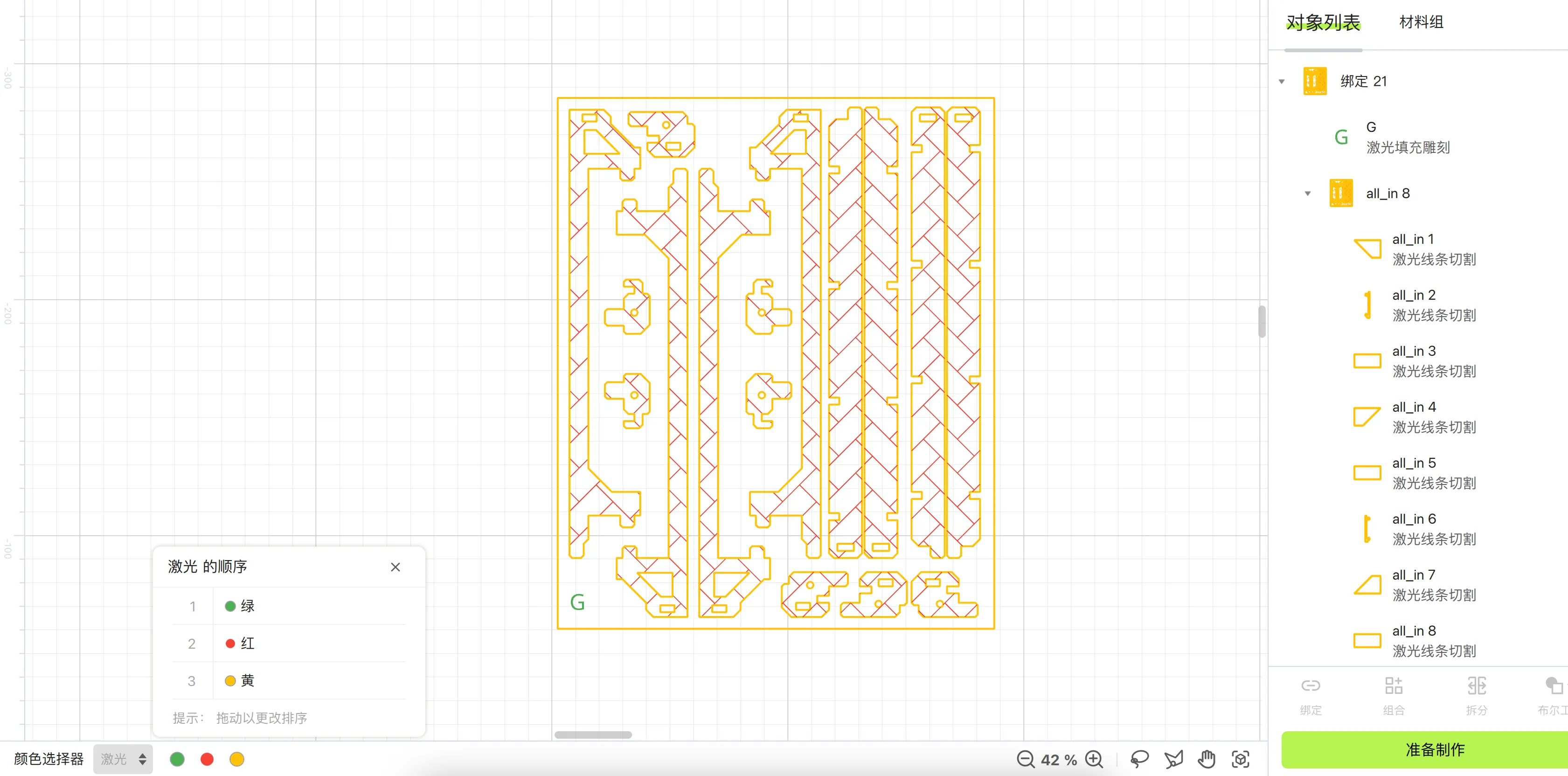
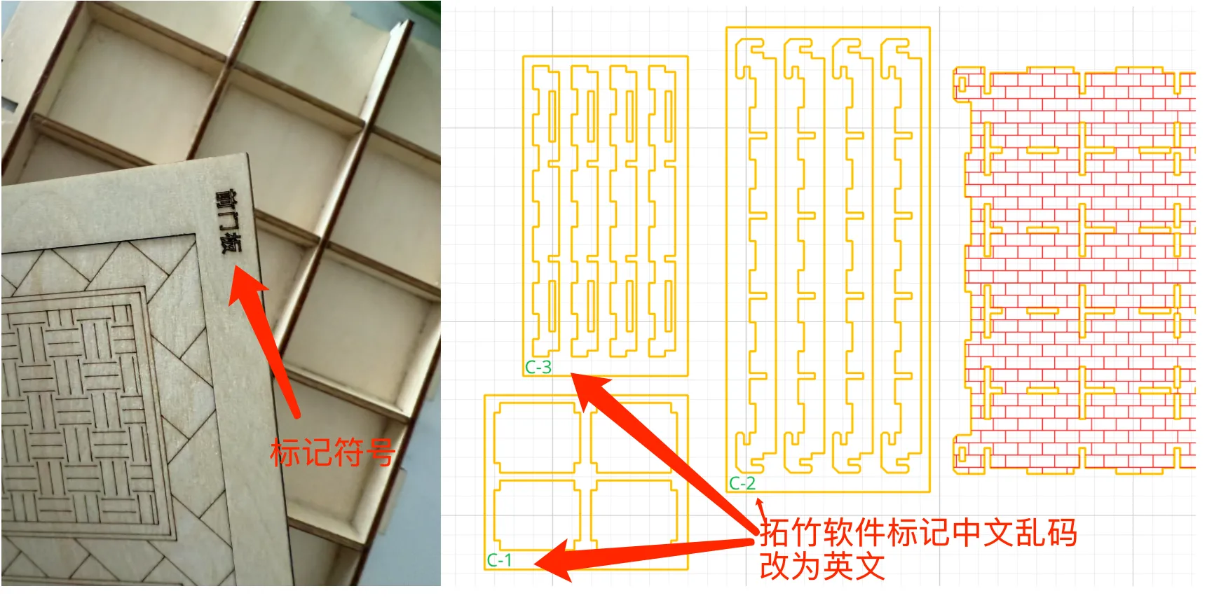
Each composite panel features design numbering.
Numbering convention: A-1, where A represents the corresponding accessory panel in a specific zone, and 1 signifies the first panel within that accessory zone. This segmentation aims to optimize material utilization within the machine's capacity.
Panels are arranged according to their respective views and combined for cutting. This approach facilitates modification and maintenance; during cutting, panels are also arranged according to plate position.
During cutting and fabrication, panels are arranged by section, potentially resulting in significant wood waste. This arrangement prioritizes ease of assembly. For users prioritizing material efficiency, adjustments may be required.
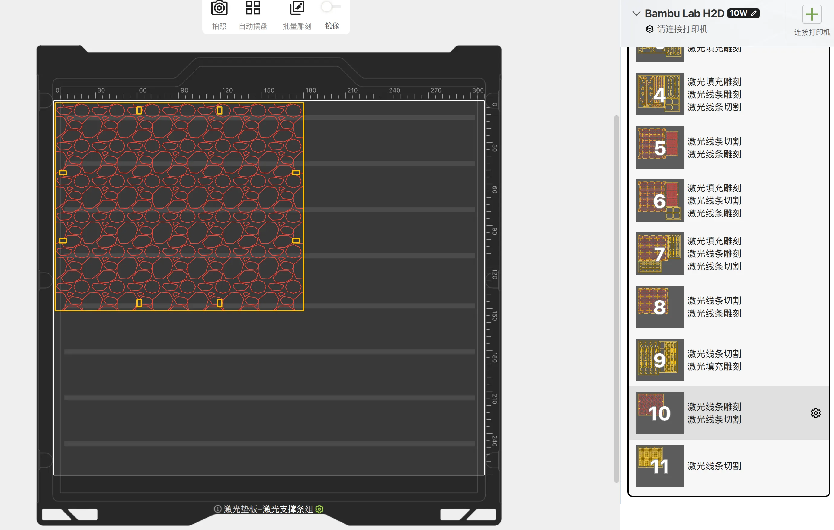
Components lack break-off designs, leading to potential scattering upon cutting. Exercise care during post-processing to organize components accordingly.
Upgrades and Optimizations
The box design has undergone enhancements, featuring an external mortise and tenon structure. The diagram maintains a 3mm hole width.
Should the actual thickness of the purchased wood be insufficient, two options exist:
- Scale the diagram. If the design is 3mm and the actual thickness is 2.7mm, apply a 0.9x scale (glass dimensions also require adjustment).
- Employ adhesive (hot melt adhesive) for reinforcement.
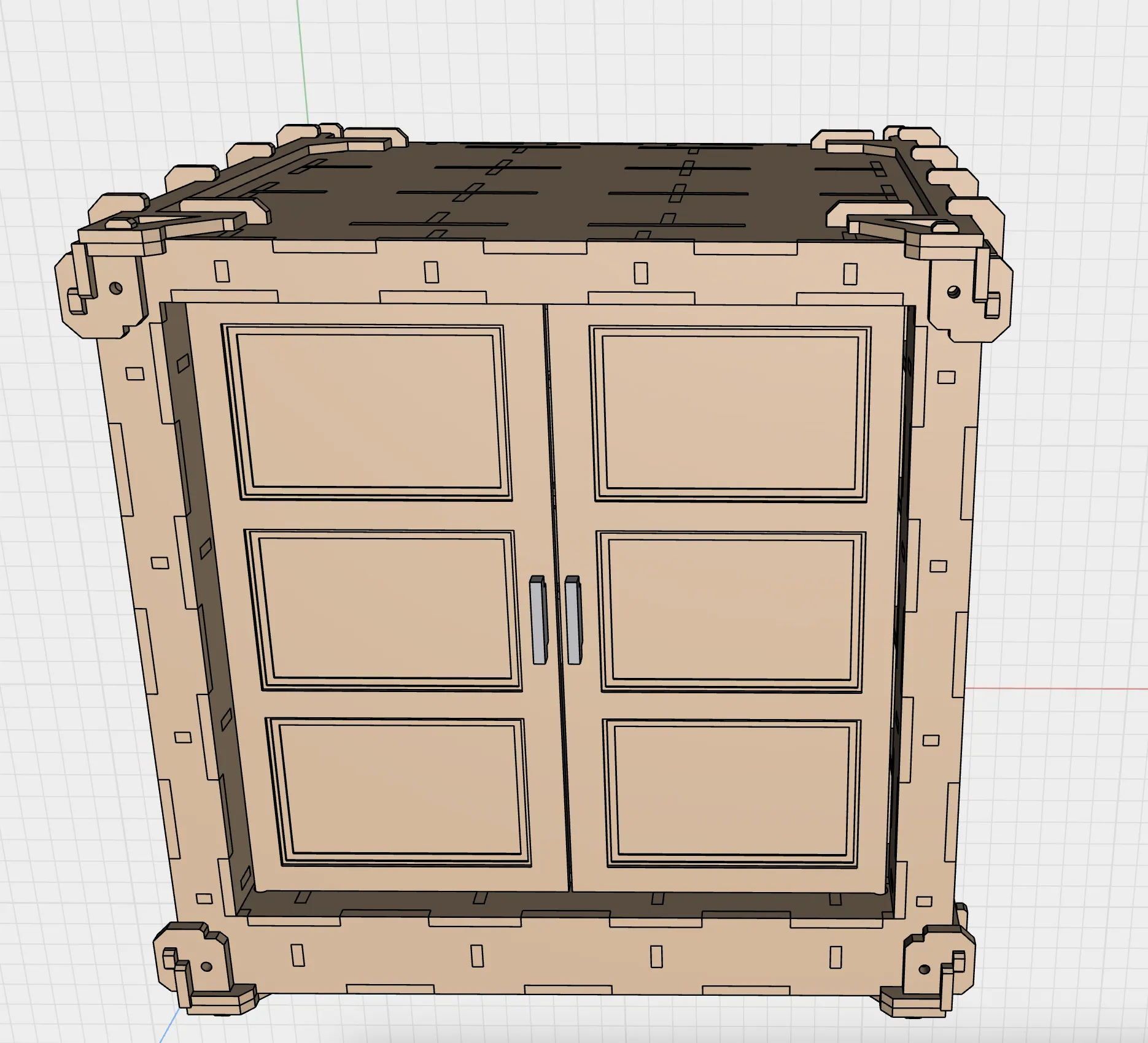
PS: Modifications for 2.7mm holes are under test; print configurations will be updated subsequently (currently awaiting wood material resupply).
Boost Me (for free)
If you like this, please boost me!
Locate the back panel and part A plates; there are three types of part A plates, four of each. Gather materials: nano adhesive, one-way mirror (200mm x 200mm), adhesive or hot melt glue.
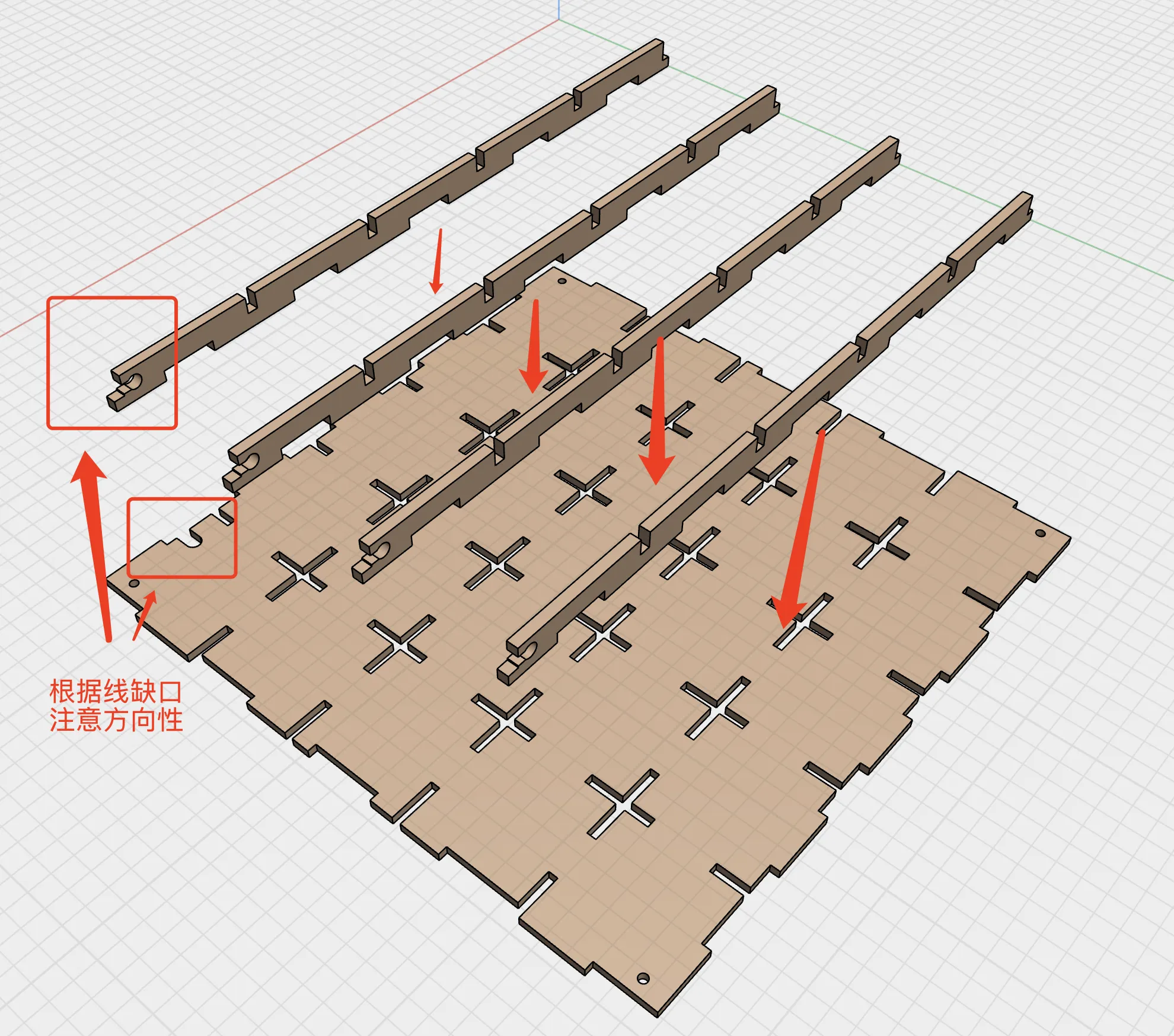
Attach the rear horizontal bars to the back panel. (Note: textured side outward, frame inward)
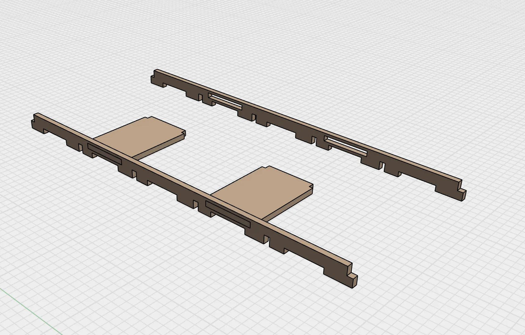
Assemble the single-mirror adhesive support plates to the rear vertical strips.
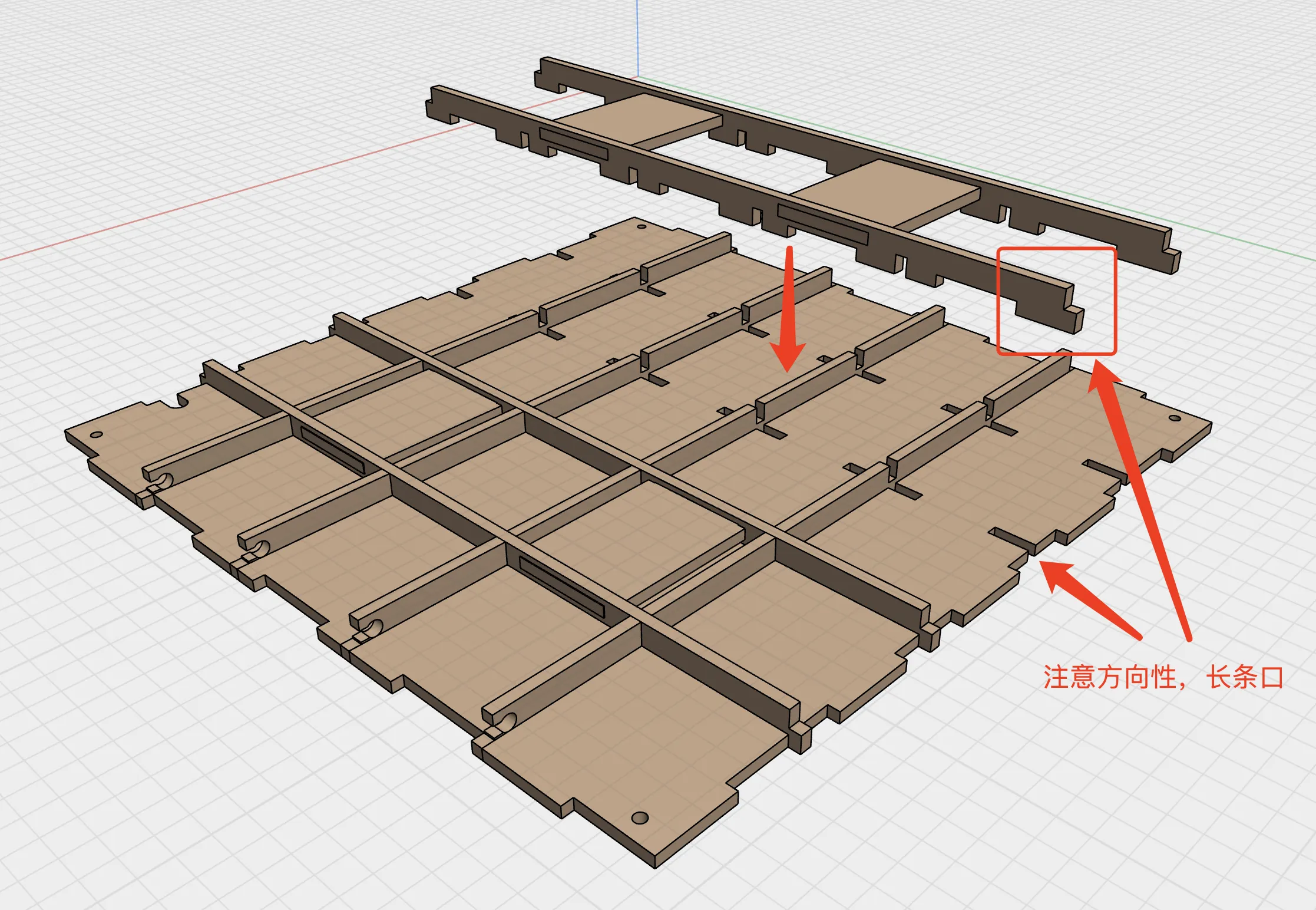
Then attach to the back panel.
Apply nano adhesive to the single-mirror adhesive support plates. After application, the height will normally be slightly higher than the frame strips.
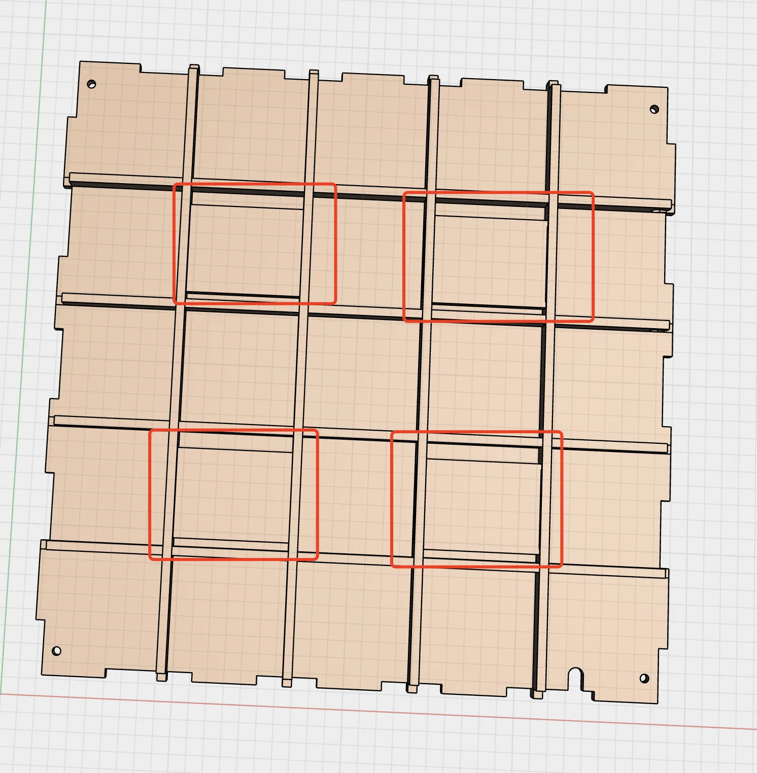
- Check for excessive looseness in the back panel; if so, reinforce with additional adhesive or hot melt glue.
Attach the one-way mirror to the back panel frame. First check the glass placement, then peel off the nano adhesive liner and apply. (Ensure proper alignment before installation; the nano adhesive and glass bond very strongly, making rework difficult)
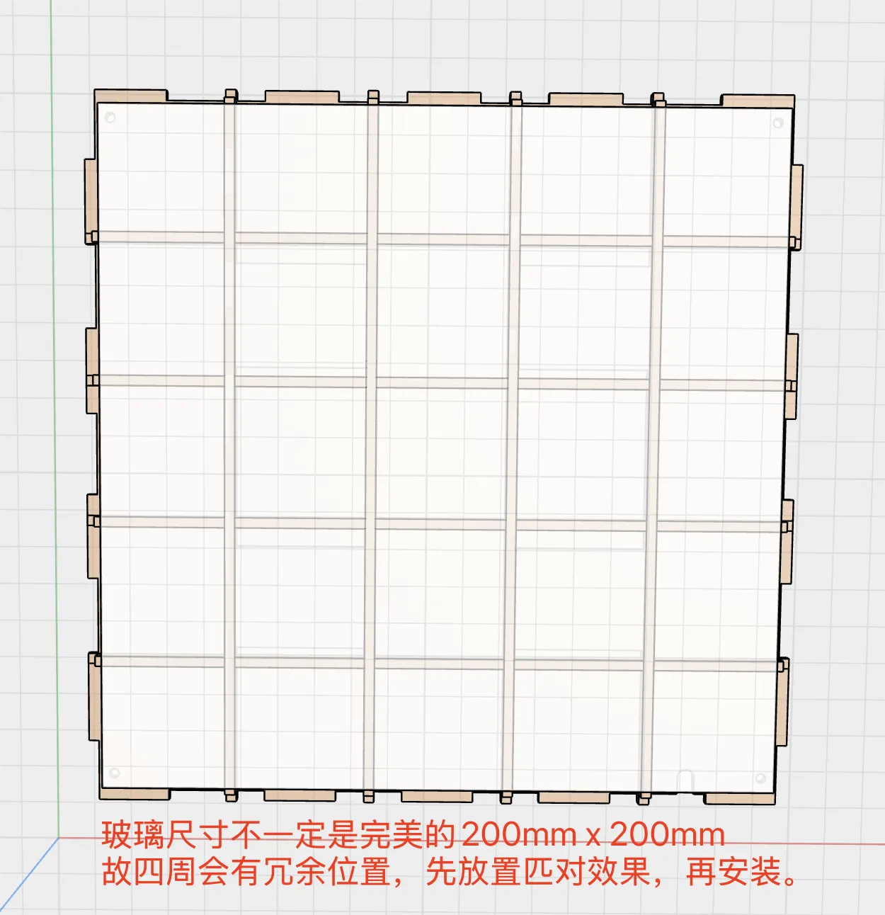
Finished product, ready for use.
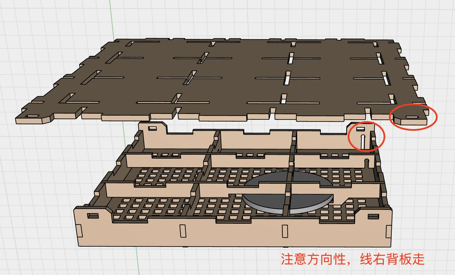
Locate the top plate, part B-1 plate, and part B-2 plate, noting the orientation of the parts within the B plates. Gather materials: Toch LED light, adhesive or hot glue.
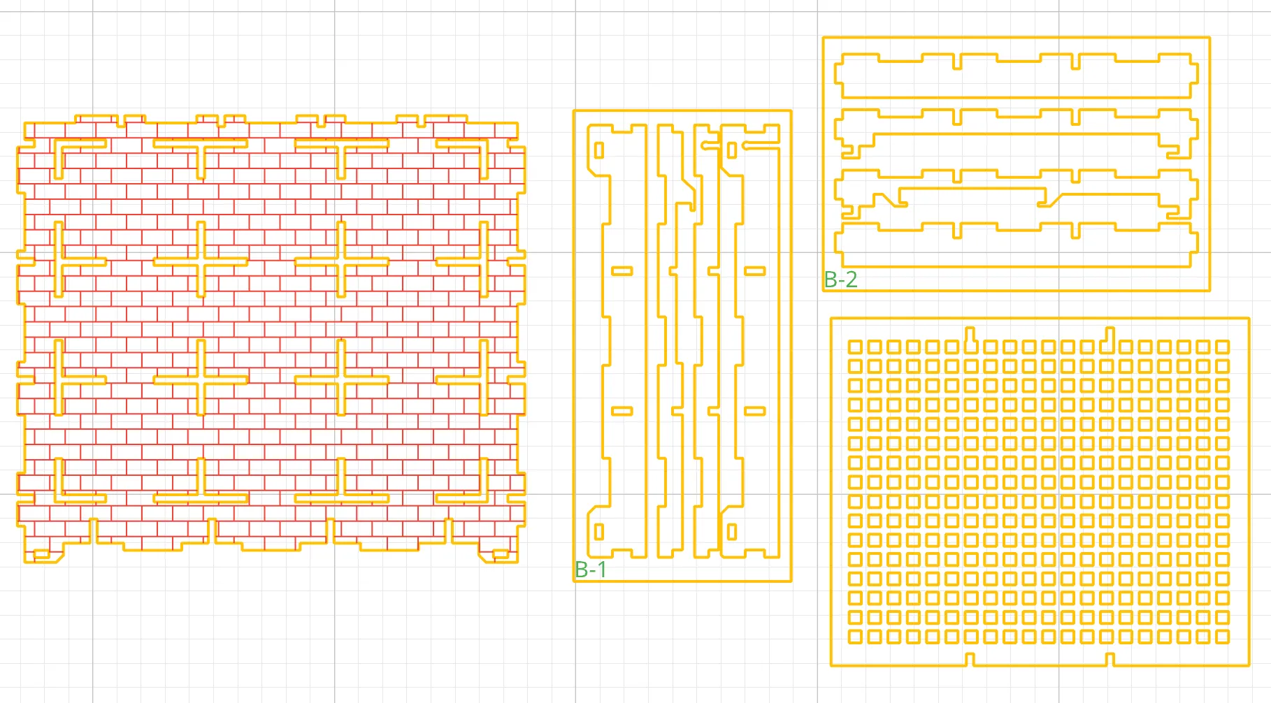
Remove the two horizontal bars from the central part B-1 plate and the two vertical bars from the central part B-2 plate.
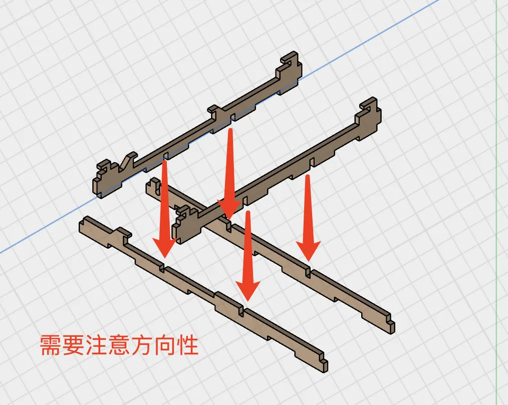
Install the LED light. Ensure the wires are securely seated in the designated slots.
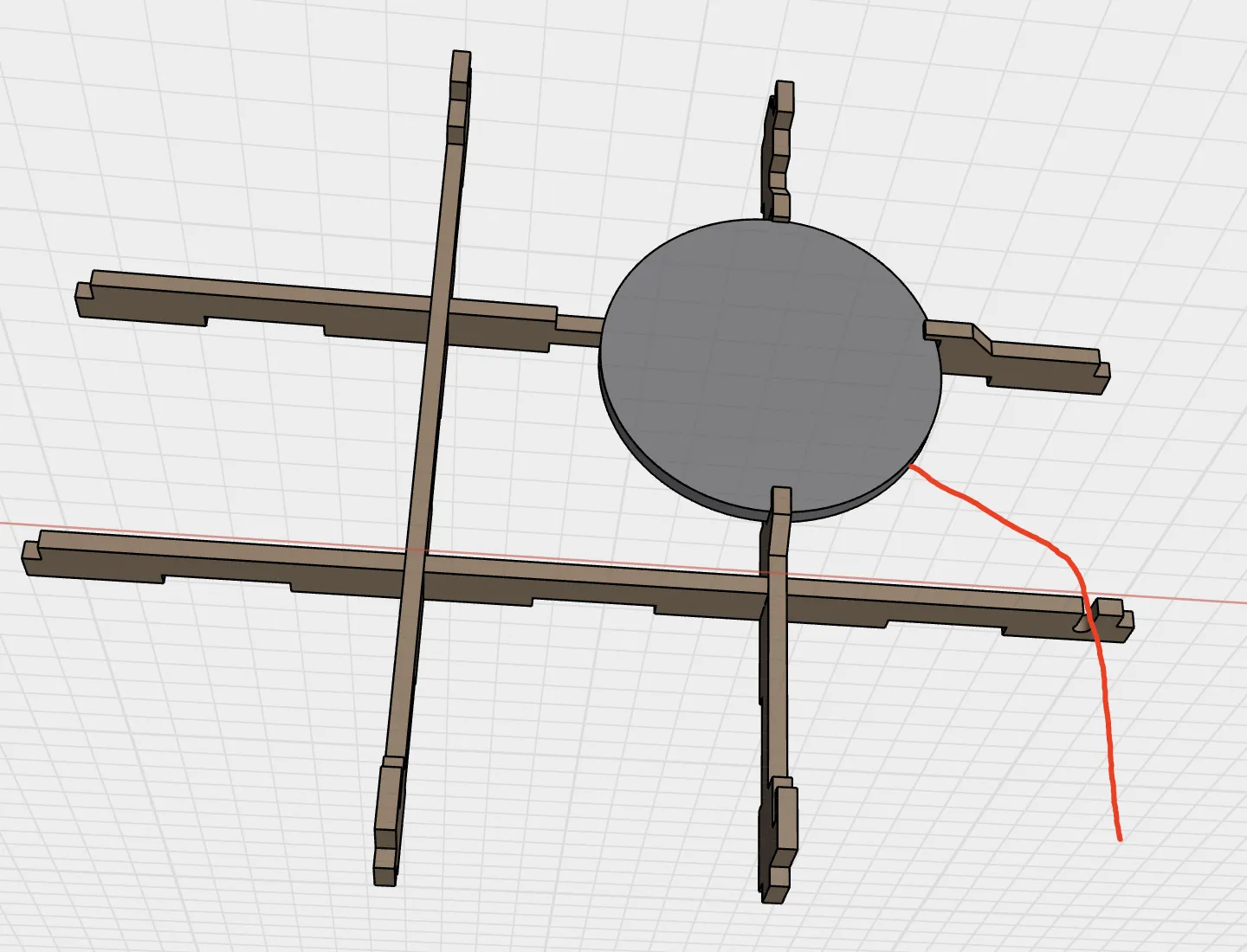
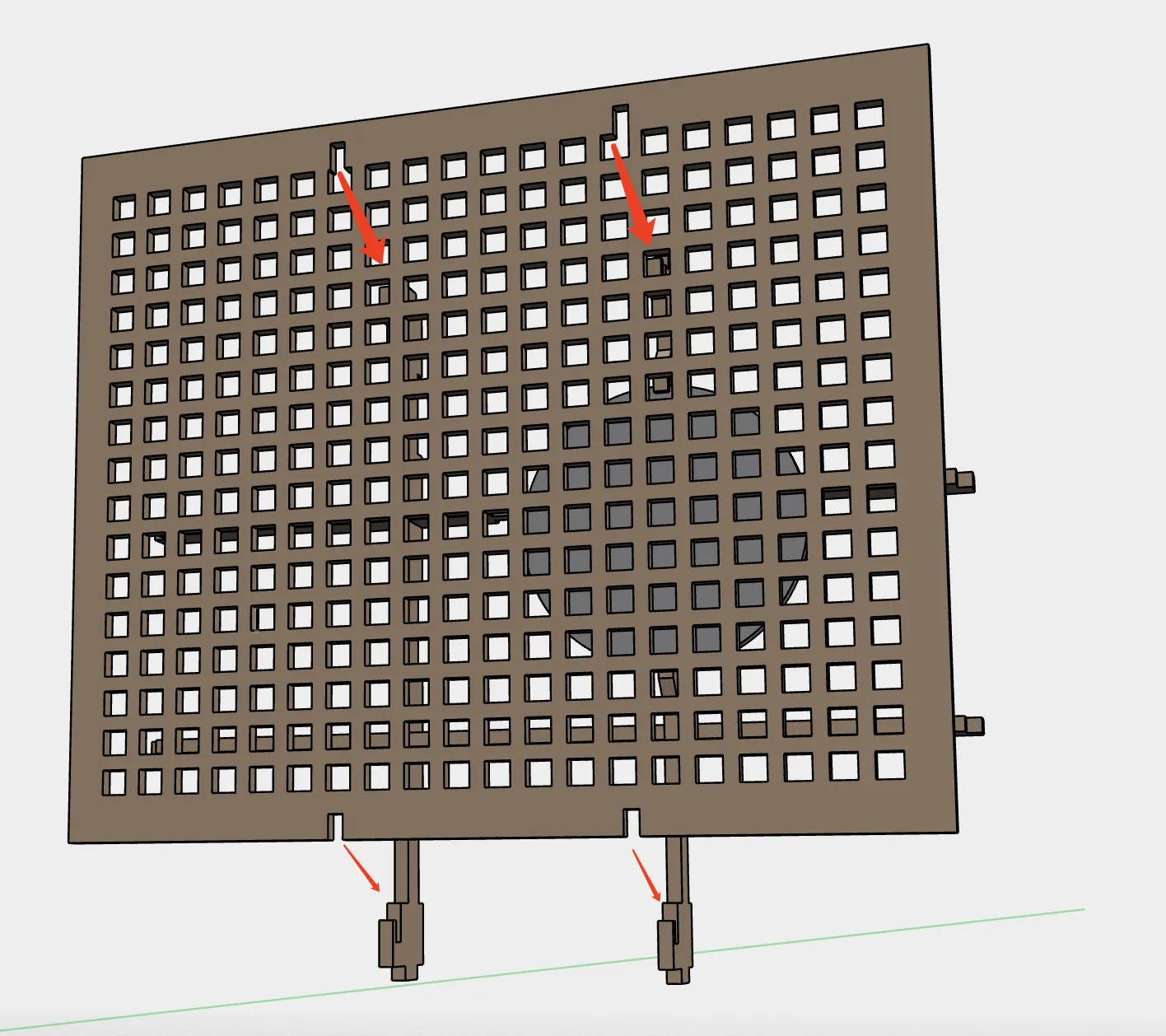
Install the perforated plate. Position the plate and slide it into place.
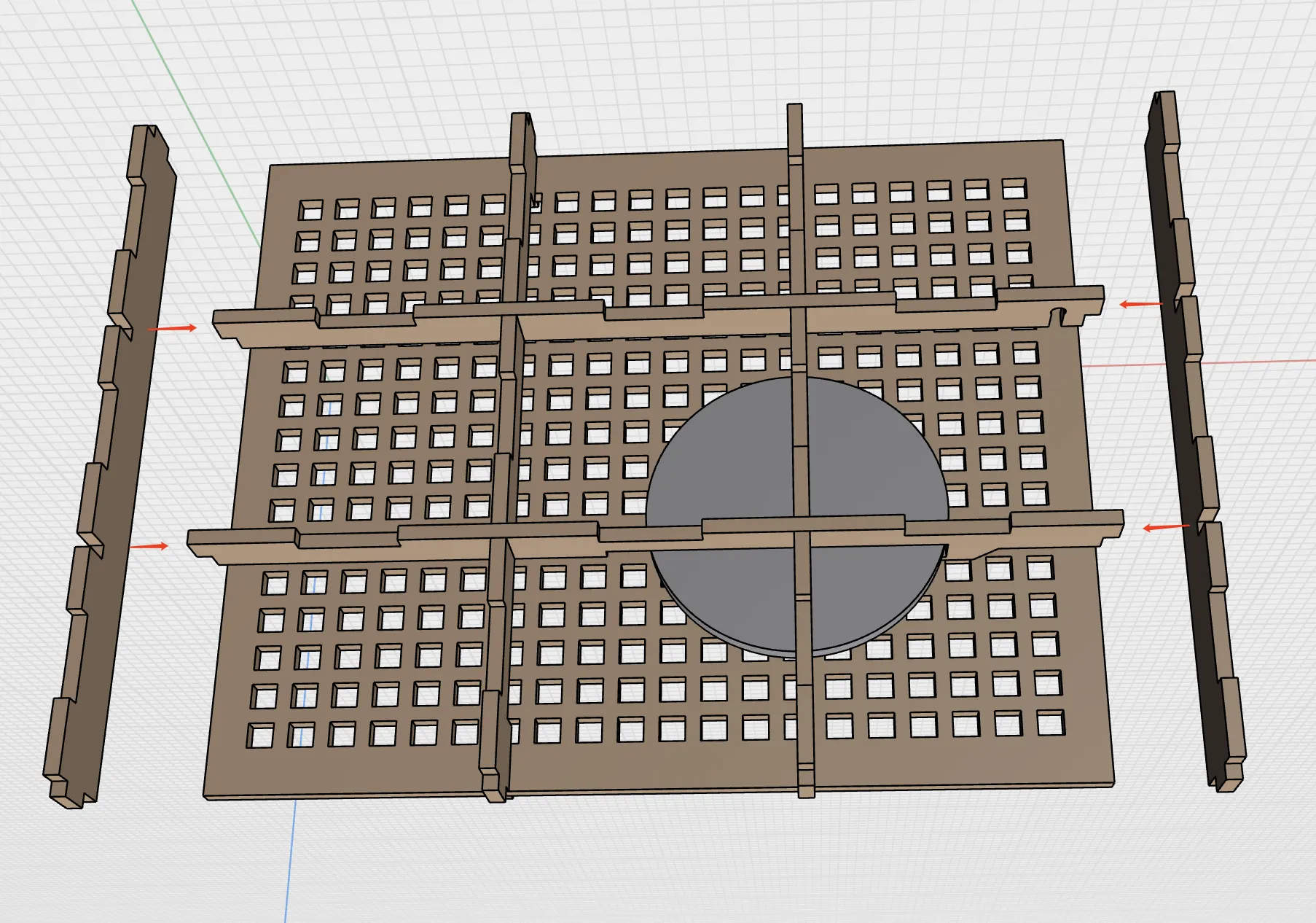
Install the side strips. Locate the remaining framework strips from the B-2 plate and insert them.
Install the hanging strips. Locate the hanging strips from the B-1 plate, first securing the LED wires, then inserting the strips.
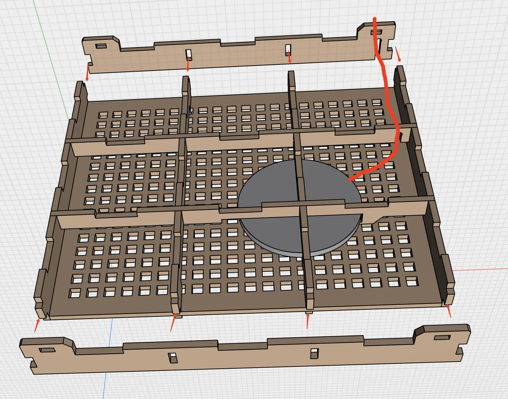
Snap in the top plate. Note the orientation; the wires run along the back, and the side with the holes is the front.(Note: textured surface faces outward, framework installed on the inner side)
Spare parts.
The left and right side panels are mirror-image designs; this instruction focuses primarily on the left panel
Locate the left side panel, C-1 component panel, C-2 component panel, and C-3 component panel Gather materials: translucent lens (150mm x 200mm), nano adhesive, adhesive, or hot melt adhesive
Attach the translucent lens adhesive support plate to the lateral cross-member
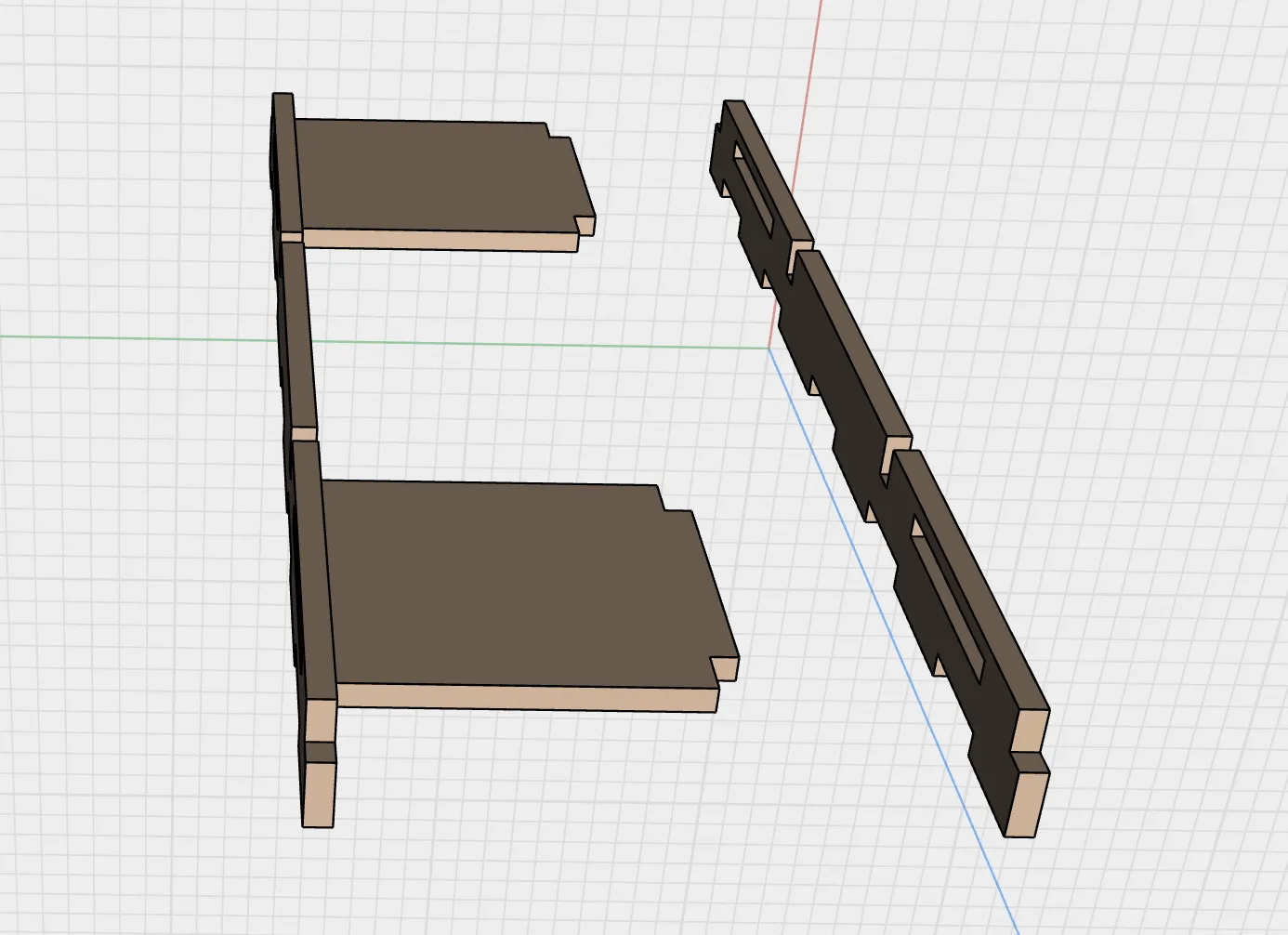
Install the lateral cross-member onto the left side panel (Note: textured side faces outward; frame installs inward)
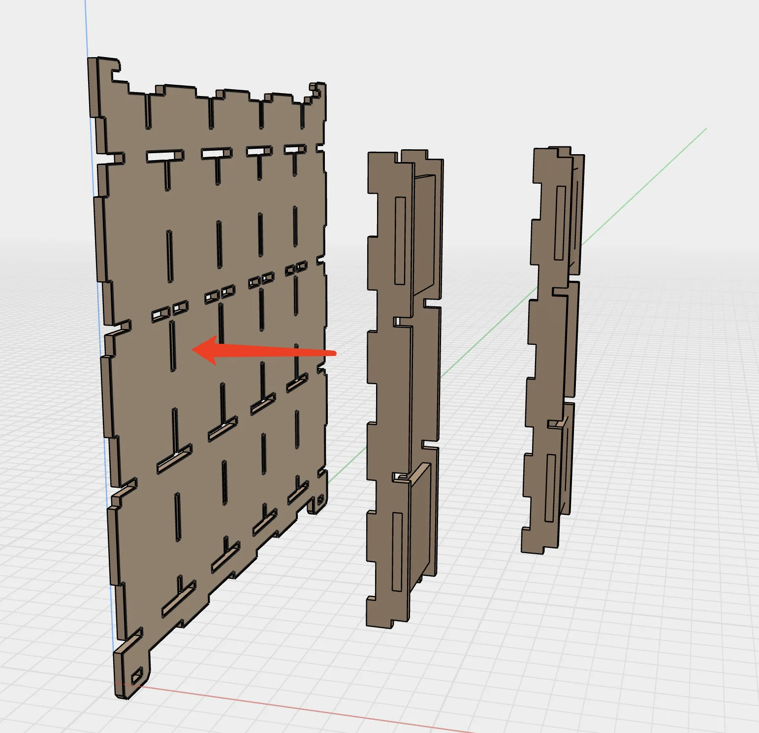
Install the vertical side member
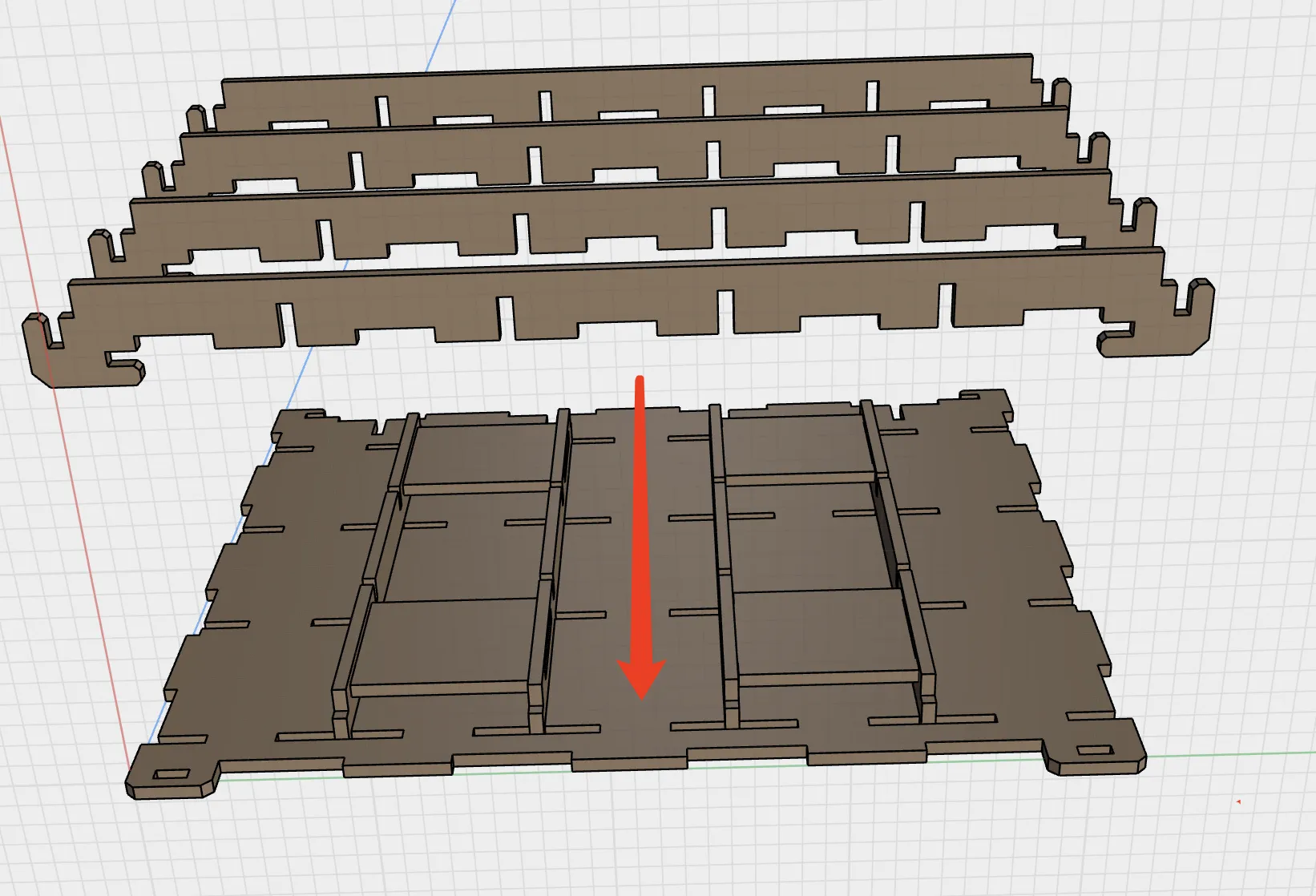
Apply nano adhesive to the support plate After application, the height will typically be slightly greater than the frame member
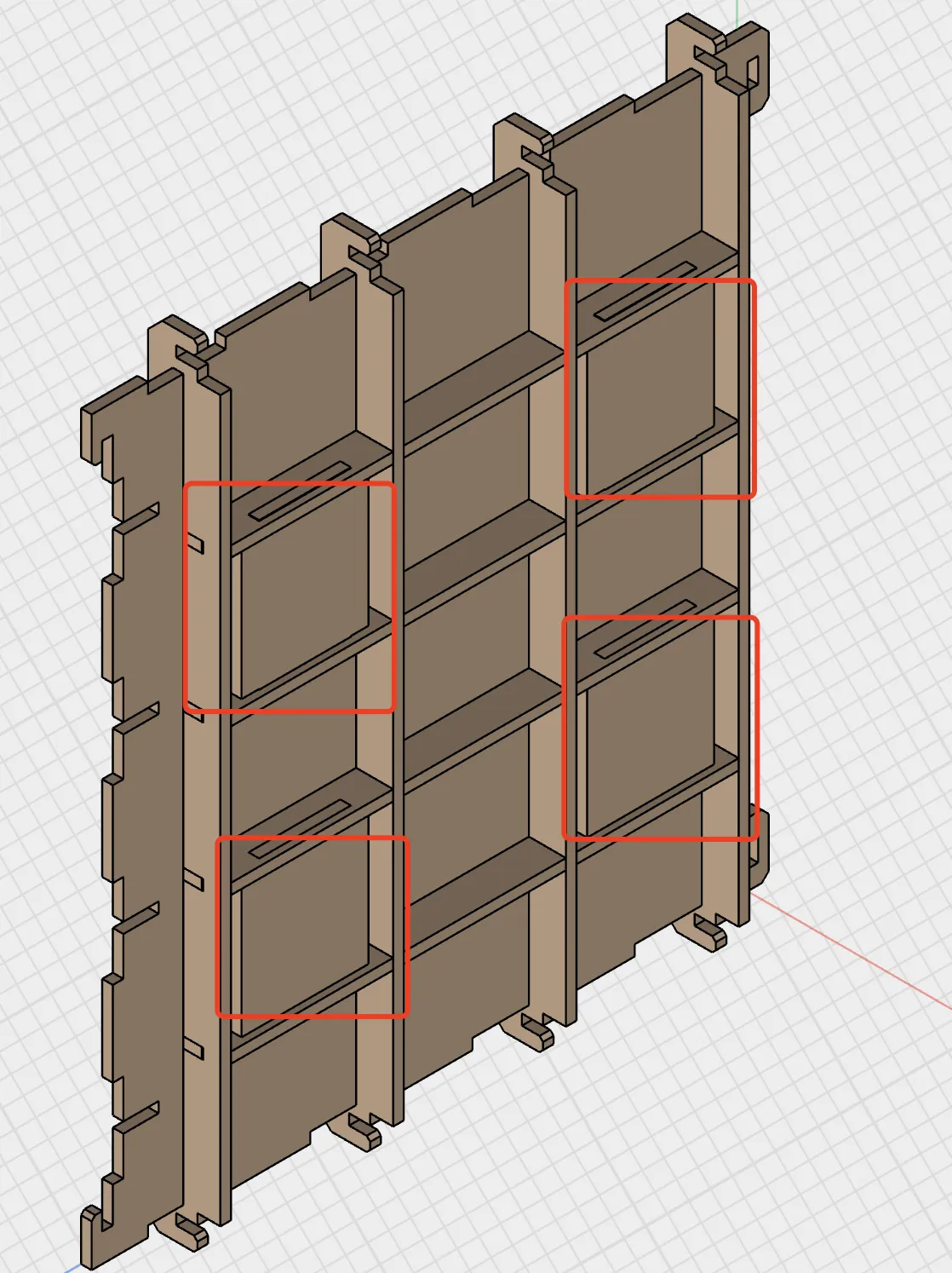
- Inspect the side panel for excessive looseness If so, reinforce with adhesive or hot melt adhesive as needed
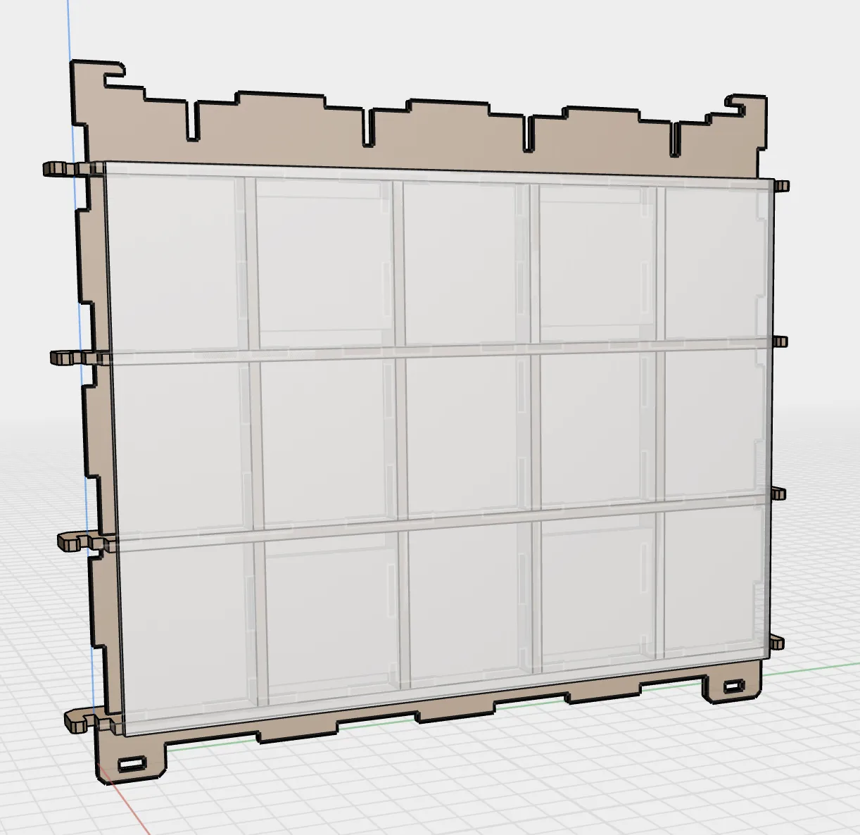
Install the translucent lens onto the side panel frame First check the glass placement, then peel off the nano adhesive liner and adhere (Always pre-align before installation; the nano adhesive and glass bond very tightly, making rework difficult)
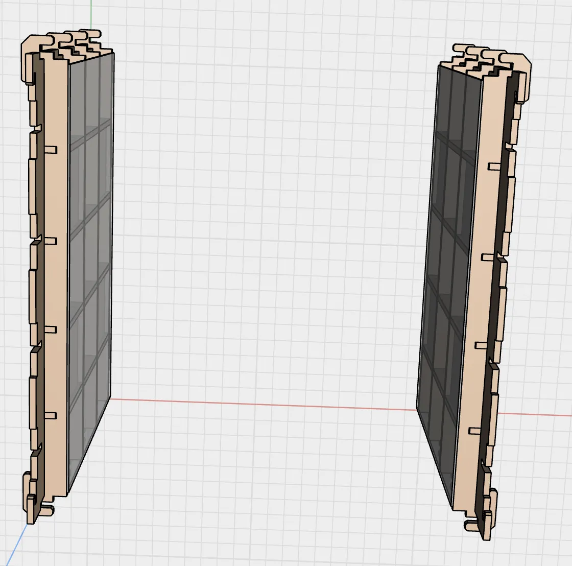
Similarly, locate the right side panel, D-1 component panel, and D-2 component panel Gather materials: translucent lens (150mm x 200mm), nano adhesive, adhesive, or hot melt adhesive Install the right side panel in the same manner
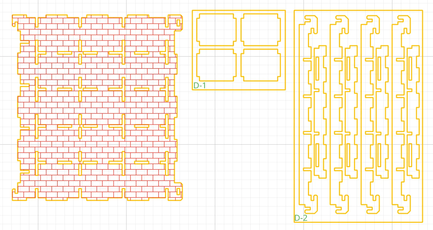
Once both left and right panels are installed, set aside
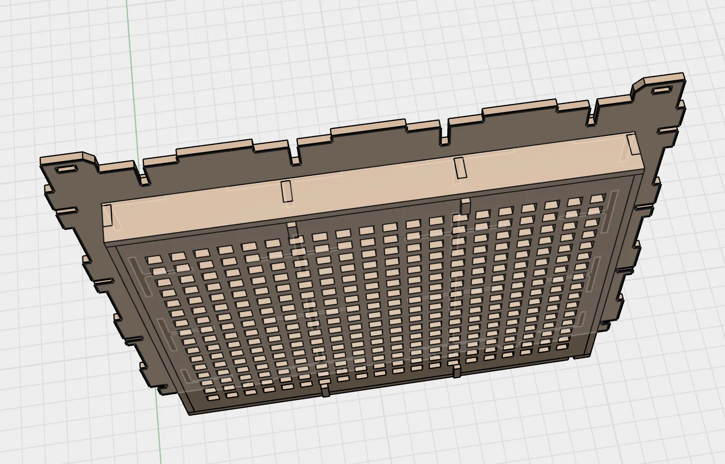
Locate the base plate, inner base plate, E-1 part plate, and E-2 part plate Gather your materials: adhesive or hot glue
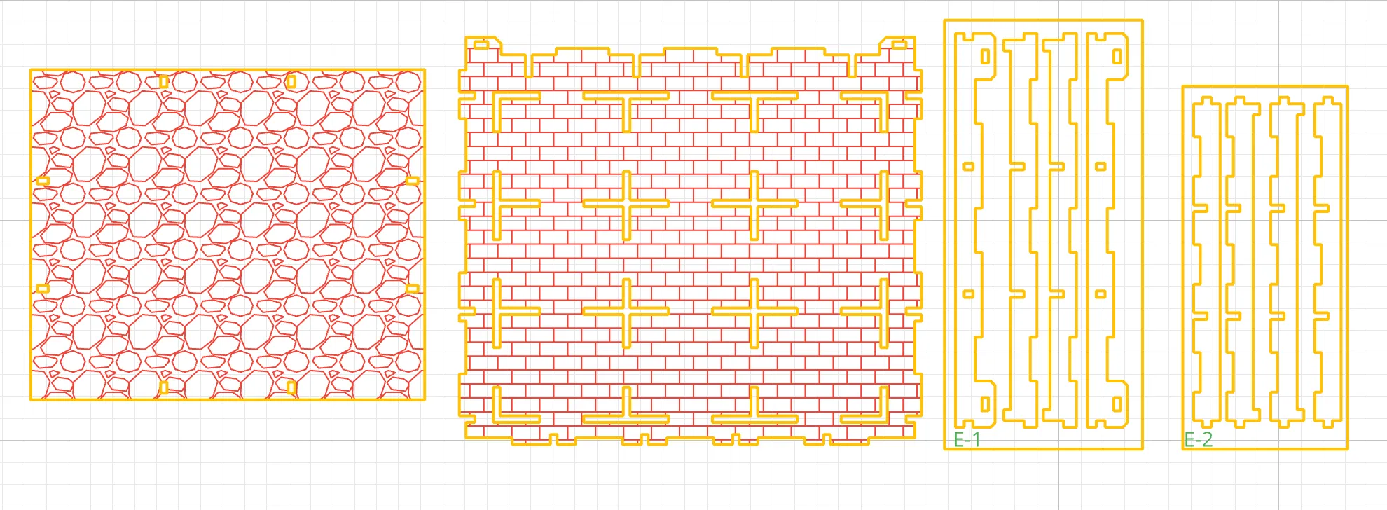
Identify the two central horizontal bars on the E-1 plate and the two central vertical bars on the E-2 plate Install by snapping them into place
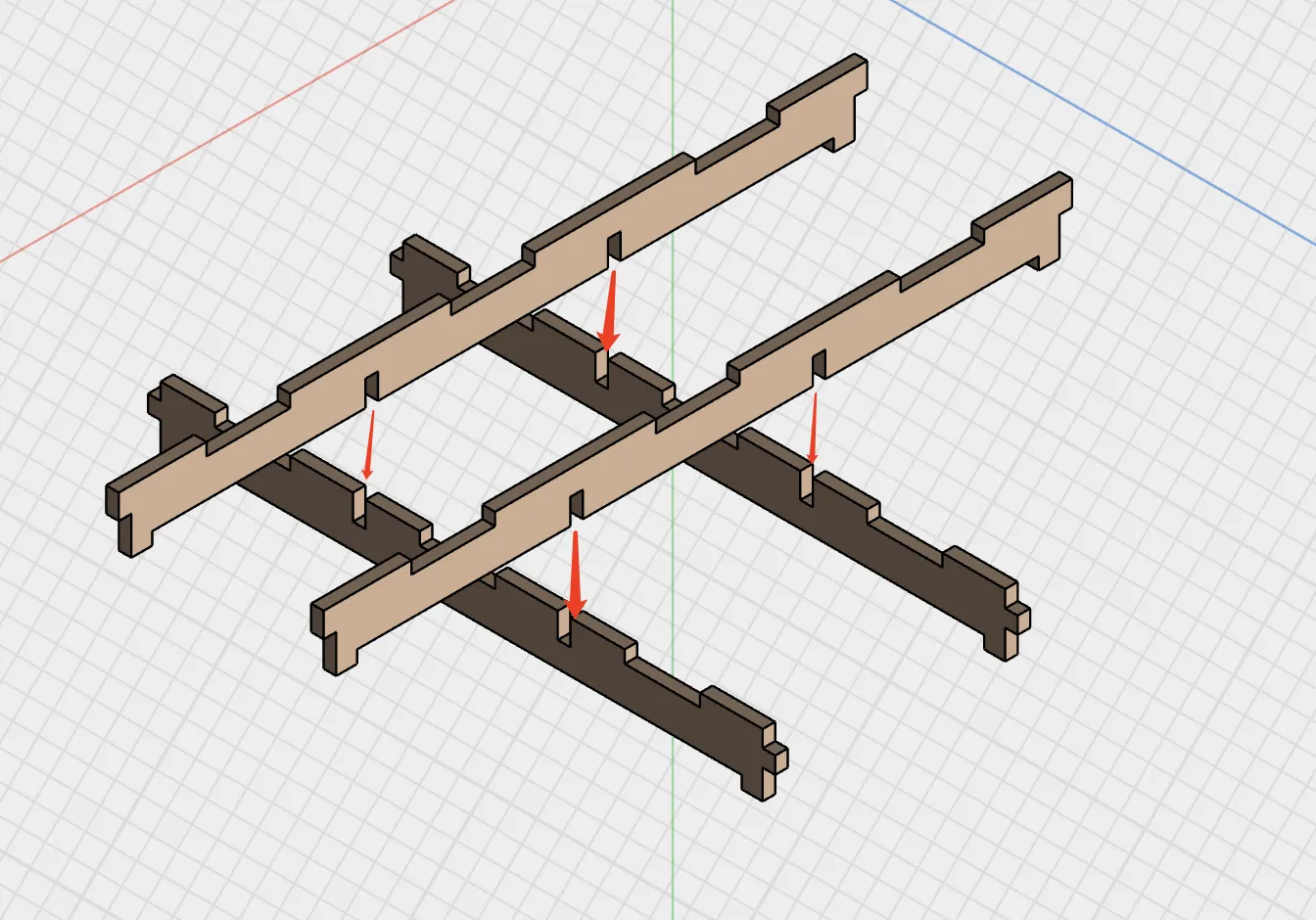
Install the lateral vertical bars Locate and attach the remaining side vertical bars from the E-2 part plate
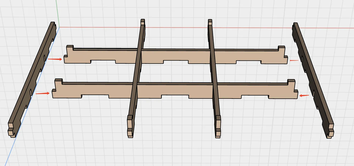
Install the lower hanging bars Attach the remaining lower hanging bars from the E-1 part plate
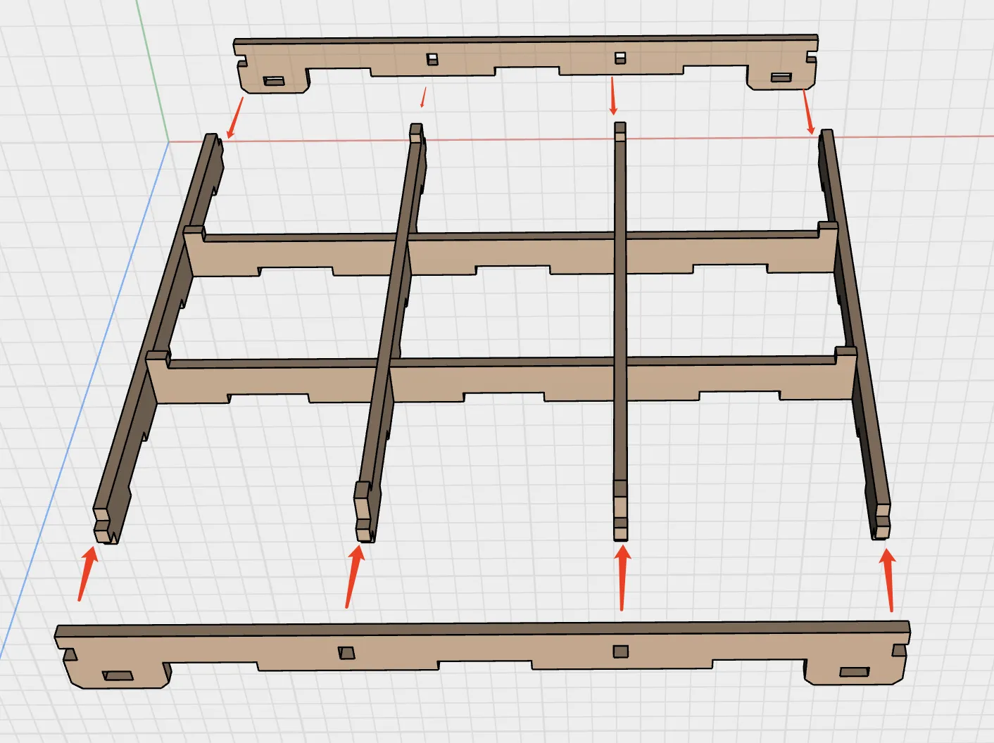
Snap in the base plate, minding the orientation (Note: textured side faces outward, frame installed inward)
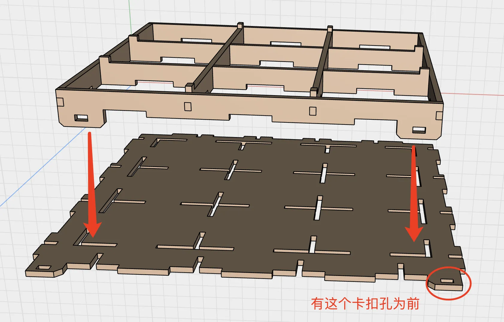
Insert the inner base plate If it feels too loose, consider using adhesive or hot glue for reinforcement (Note: textured side faces outward, frame installed inward)
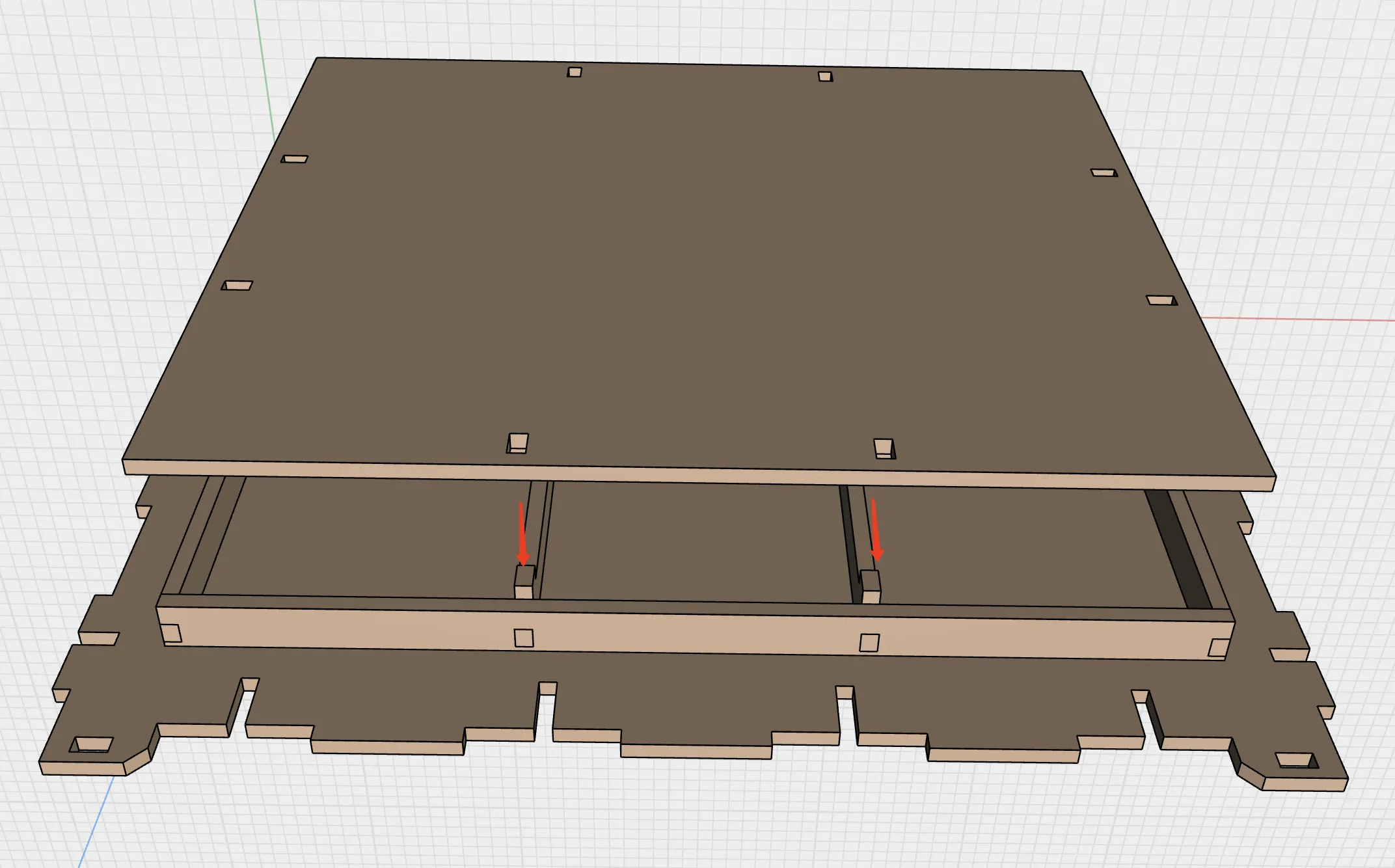
Spare parts
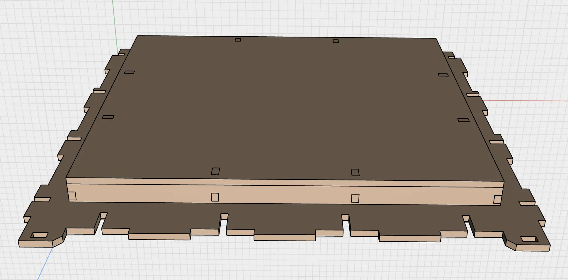
Locate the front frame, door panel, F-1 parts plate, and F-2 parts plate Gather materials: translucent lens (200mm x 200mm), nano adhesive (1mm thick x 10mm wide), magnets, and small iron pieces
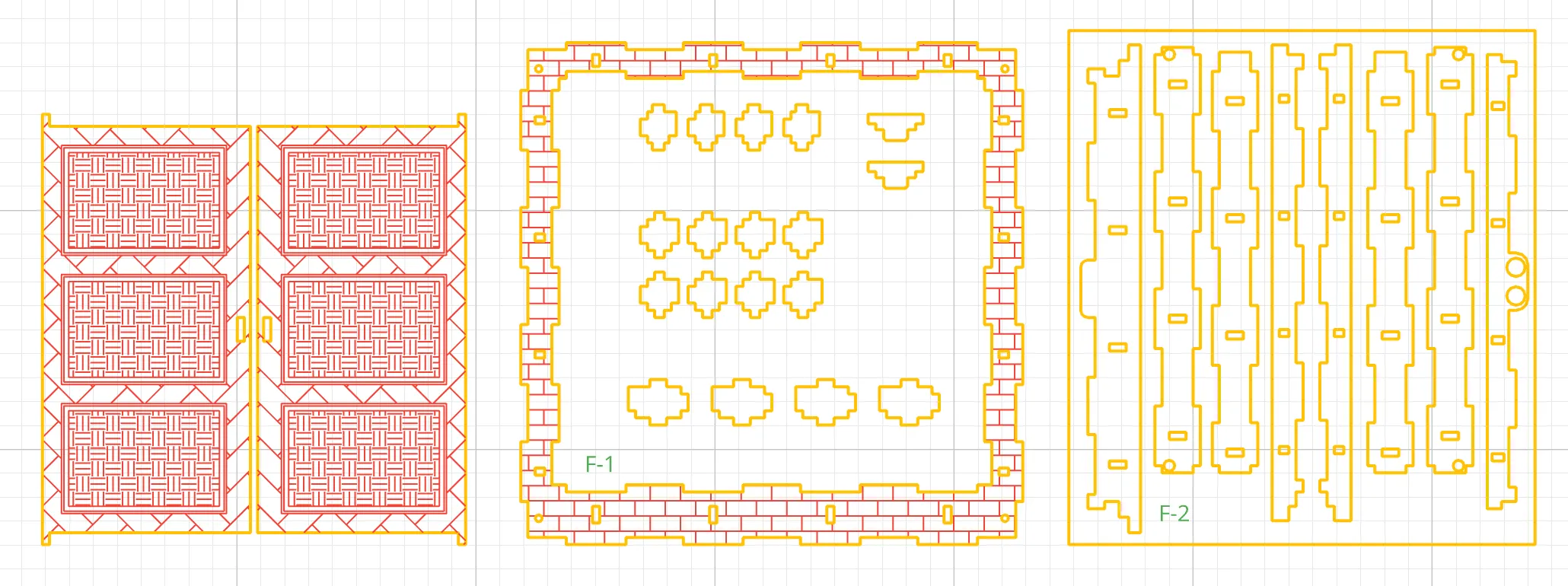
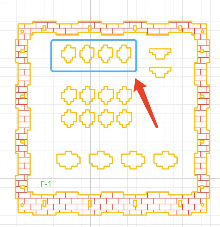
Install the front frame inner top plate assembly Detach the upper inner support block from the front plate on the F-1 parts plate Note its orientation and insert it into the front frame inner top plate
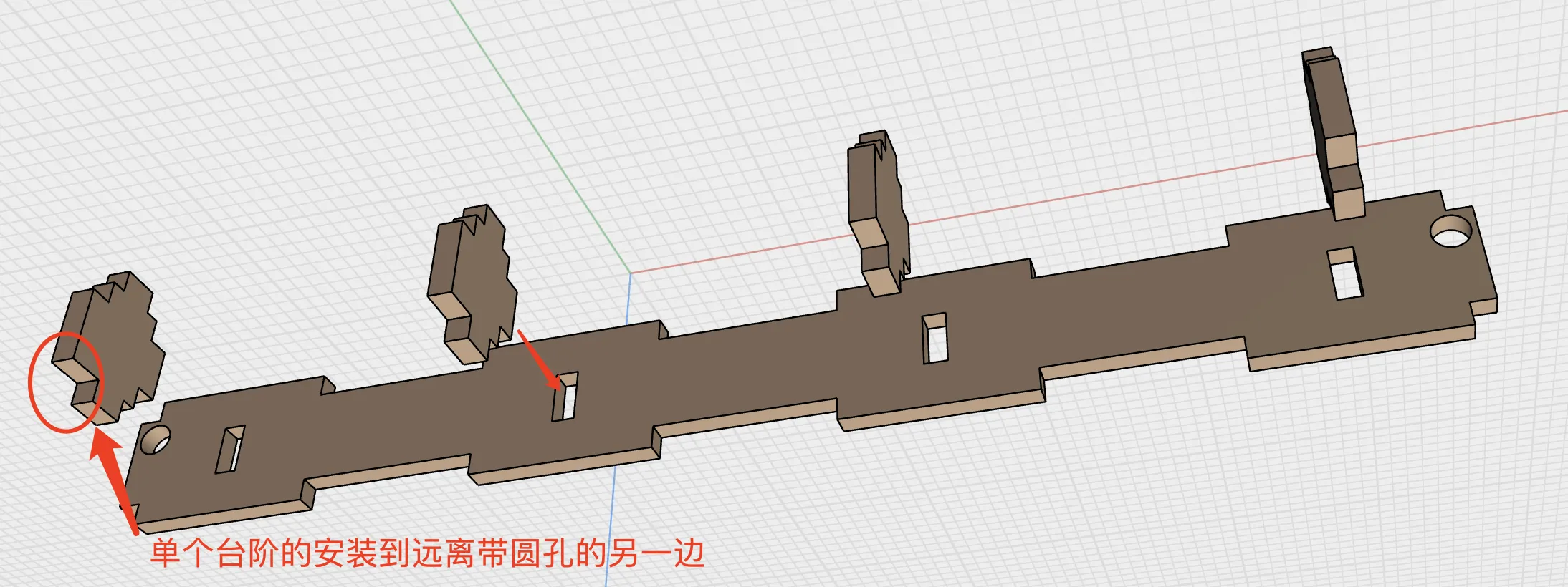
Insert the front frame inner top plate into the front frame (Ensure the textured side faces outward, and the frame is installed inward)
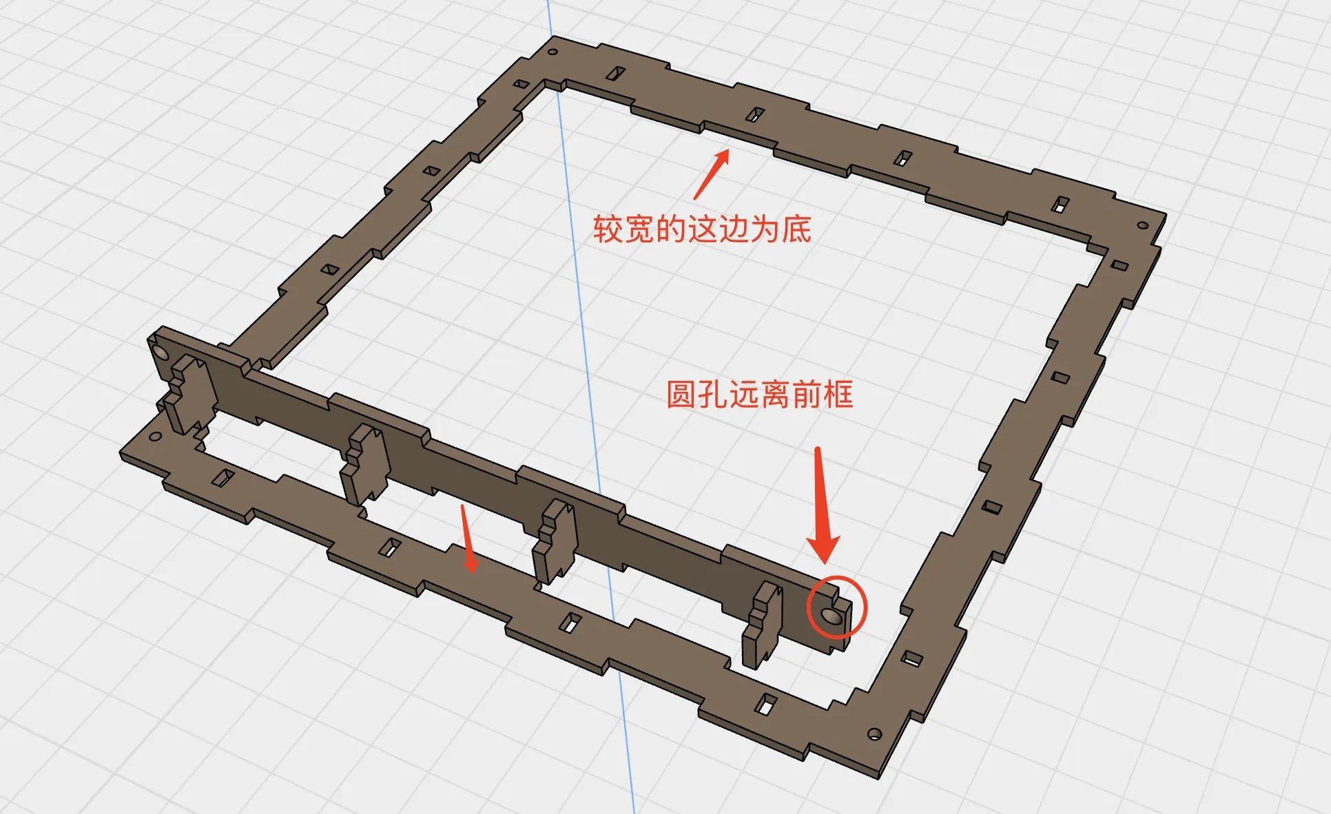
Install the left and right side plate assembly Detach the left and right inner support blocks from the F-1 parts Observe their orientation and insert them into the left and right side plates
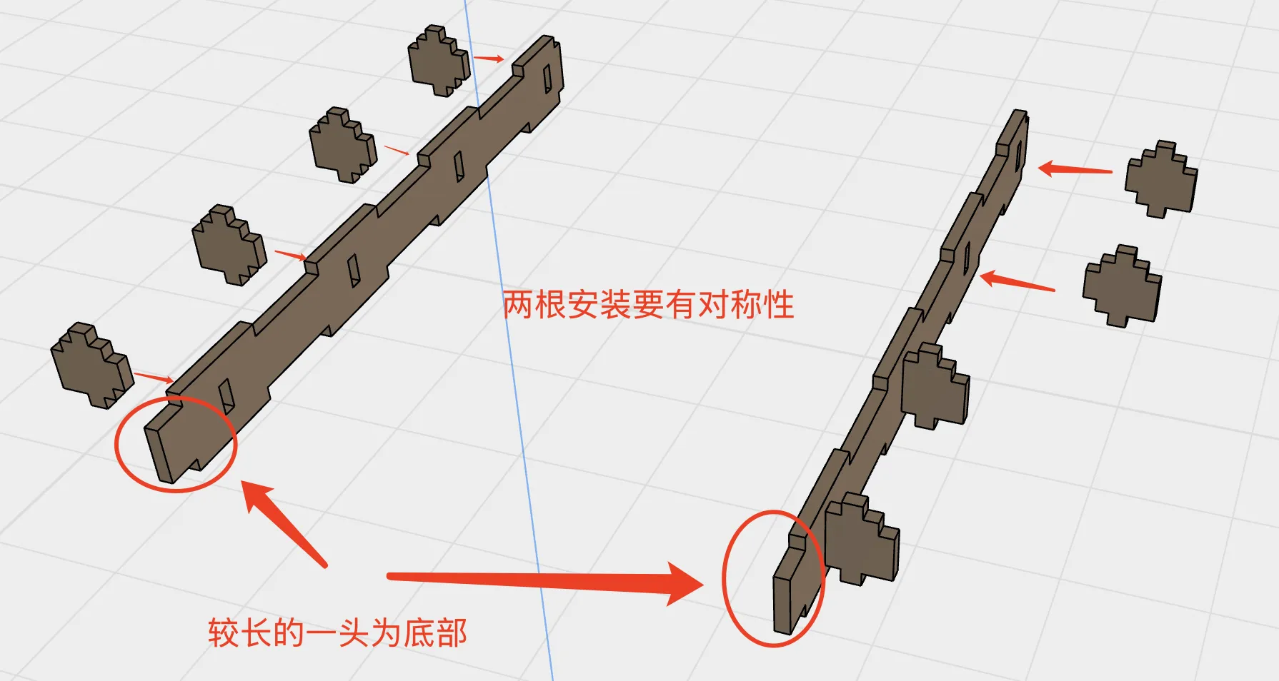
Insert the left and right side plate assembly into the front frame
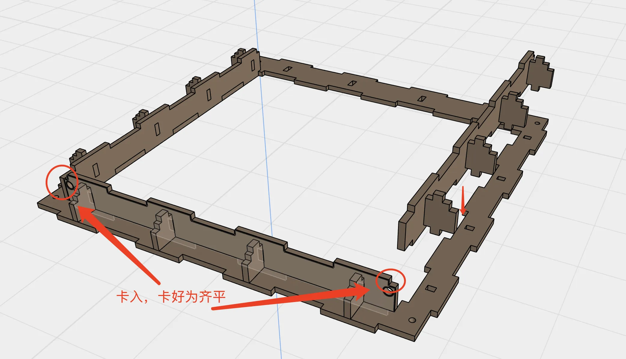
Install the front frame inner bottom plate assembly Detach the lower inner support block from the F-1 parts Note its orientation and insert it into the front frame inner top plate
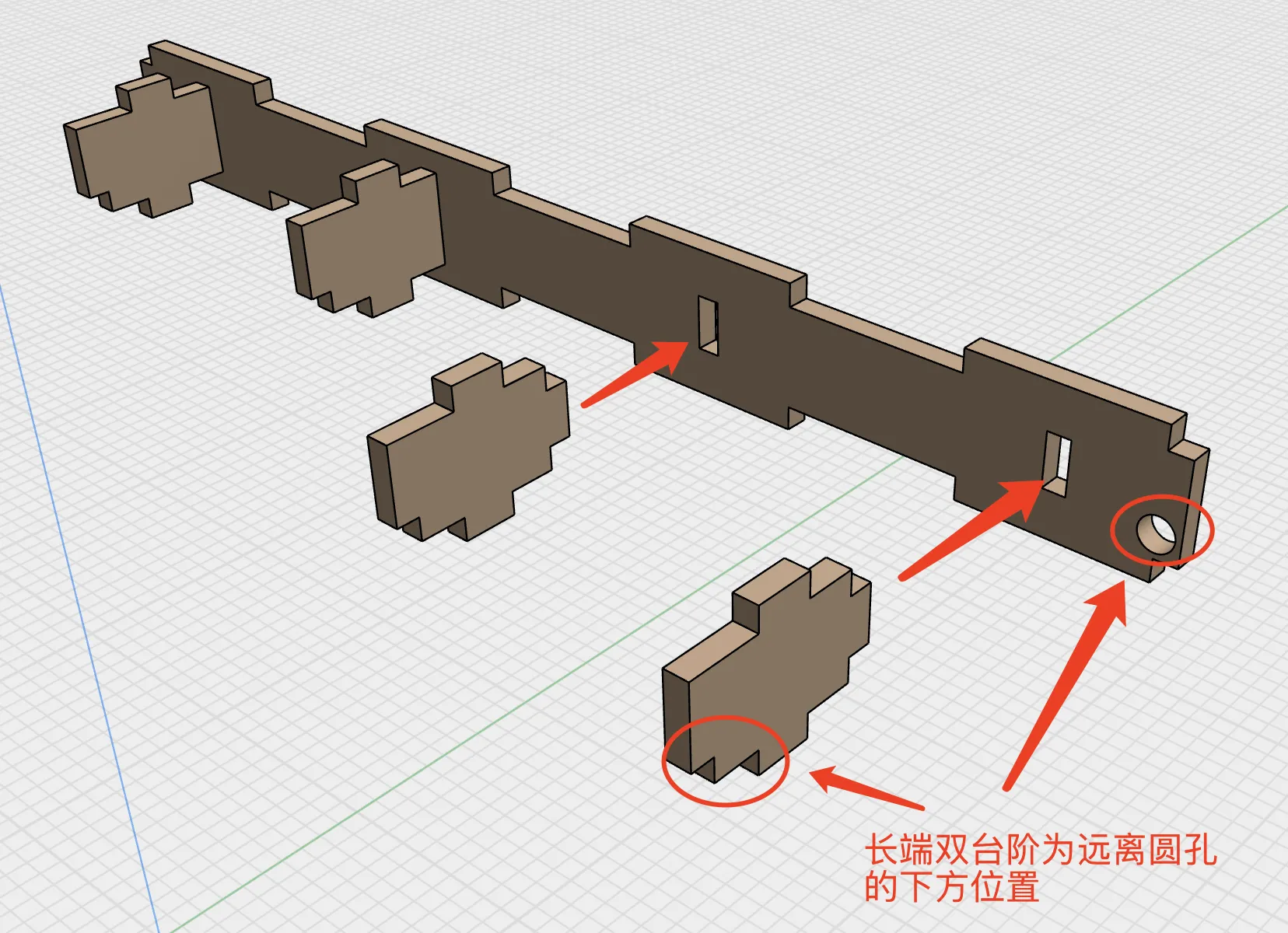
Insert the front frame inner bottom plate assembly and door panel into the front frame First insert the door into the front frame inner top plate assembly Then use the front frame inner bottom plate assembly to secure it to the front frame Check for excessive looseness and reinforce with glue or hot melt adhesive if necessary
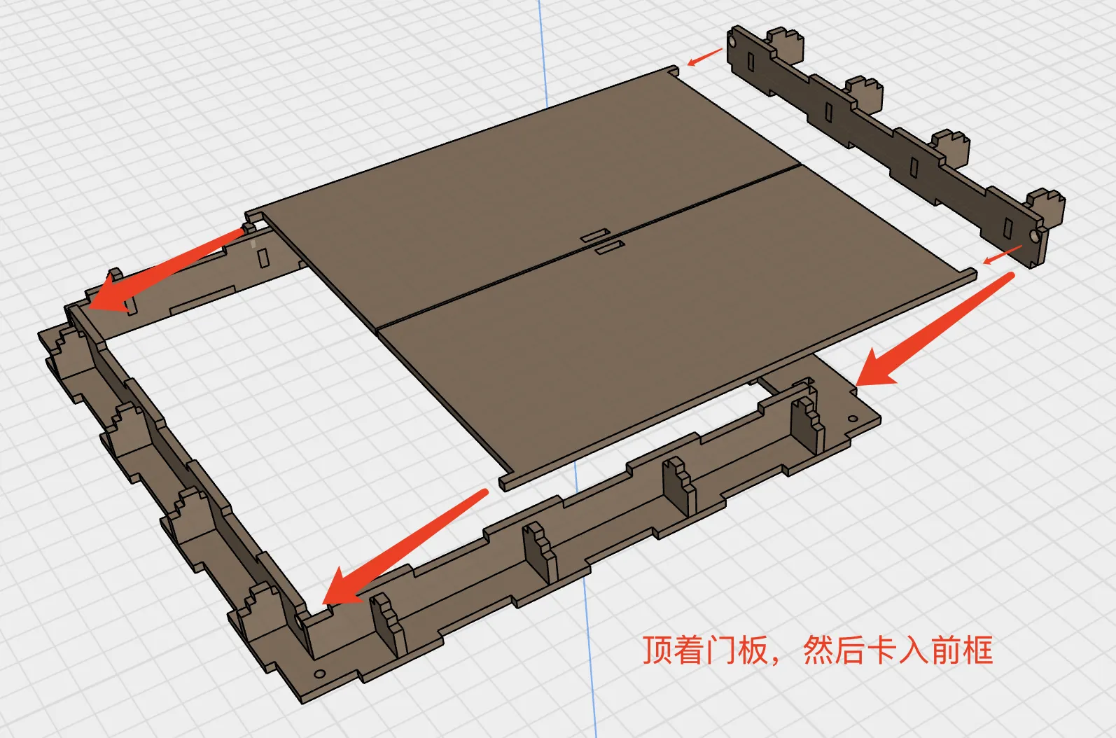
Install the inner support plates Detach the inner support plates from the F-2 parts plate and install them in the front frame
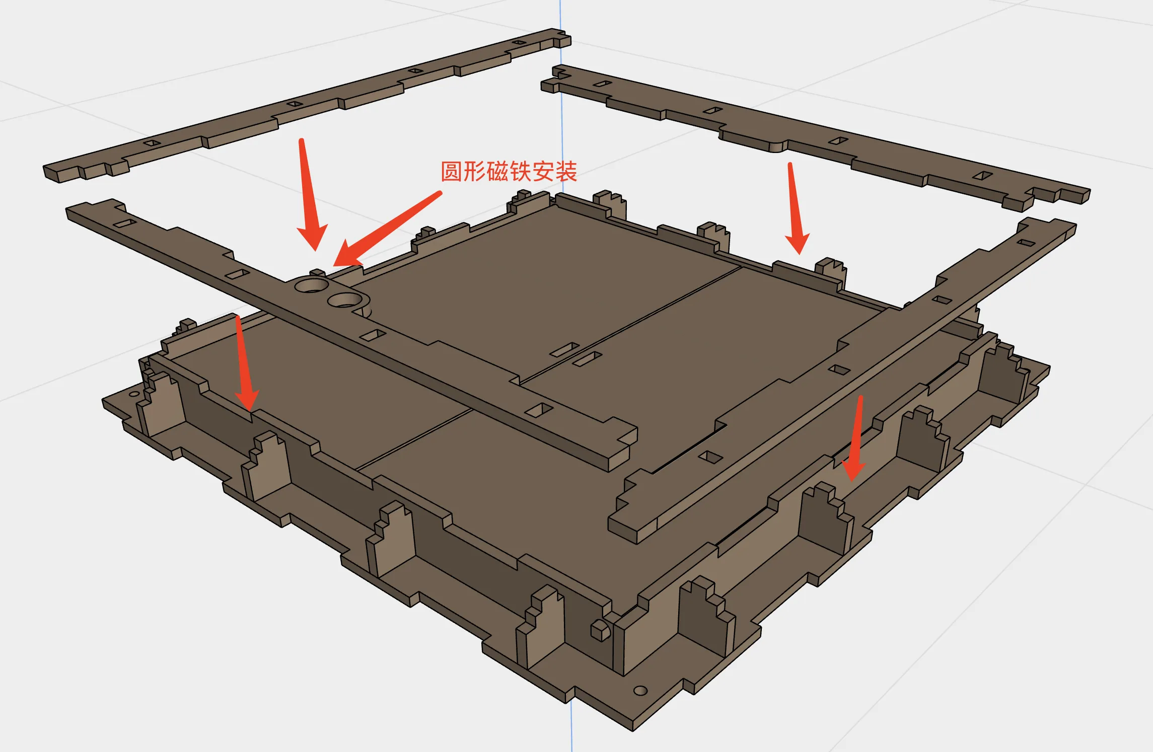
Install the door latch Detach the door latch from the F-1 parts plate and install it on the door panel Check for excessive looseness and reinforce with glue or hot melt adhesive if necessary
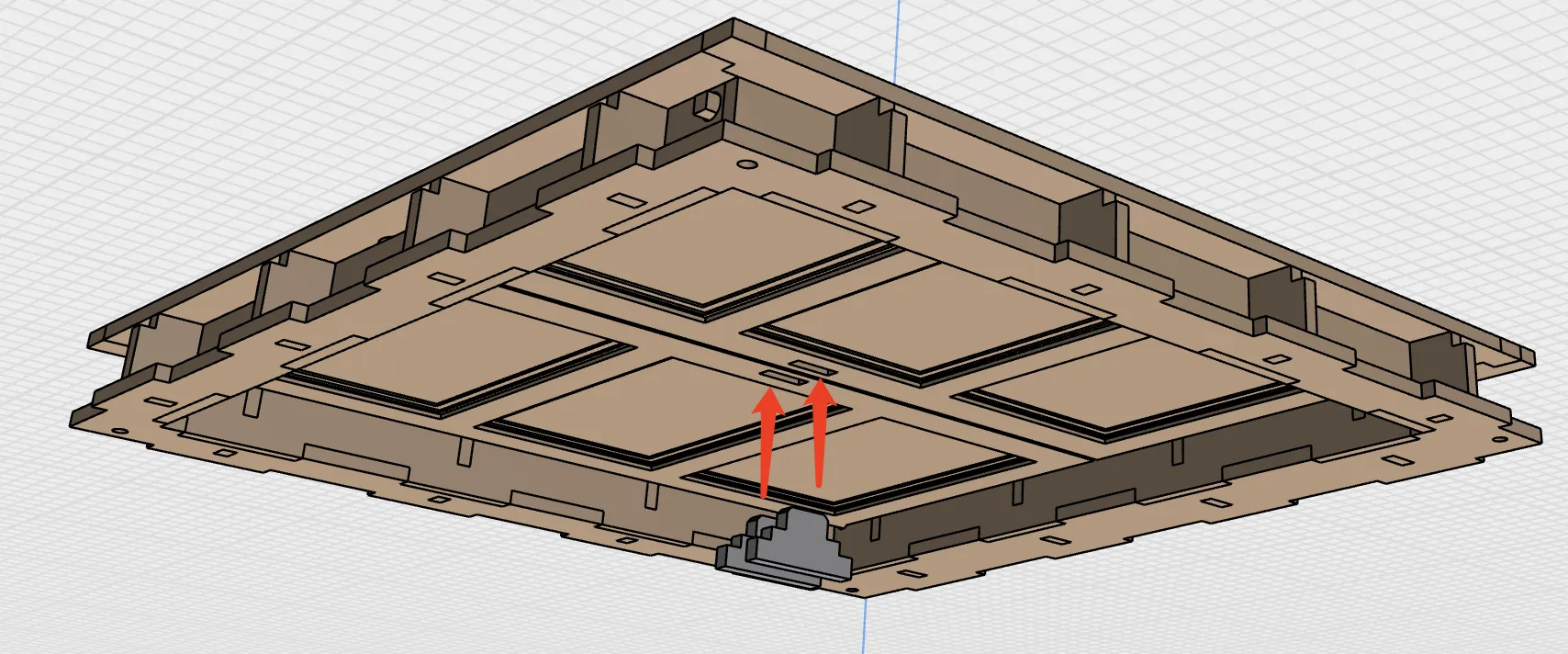
Install the translucent lens Apply nano adhesive to the inner support plates Check the glass placement before removing the nano adhesive liner and adhering the glass (Ensure proper alignment before installation Nano adhesive bonds strongly to glass making rework difficult)
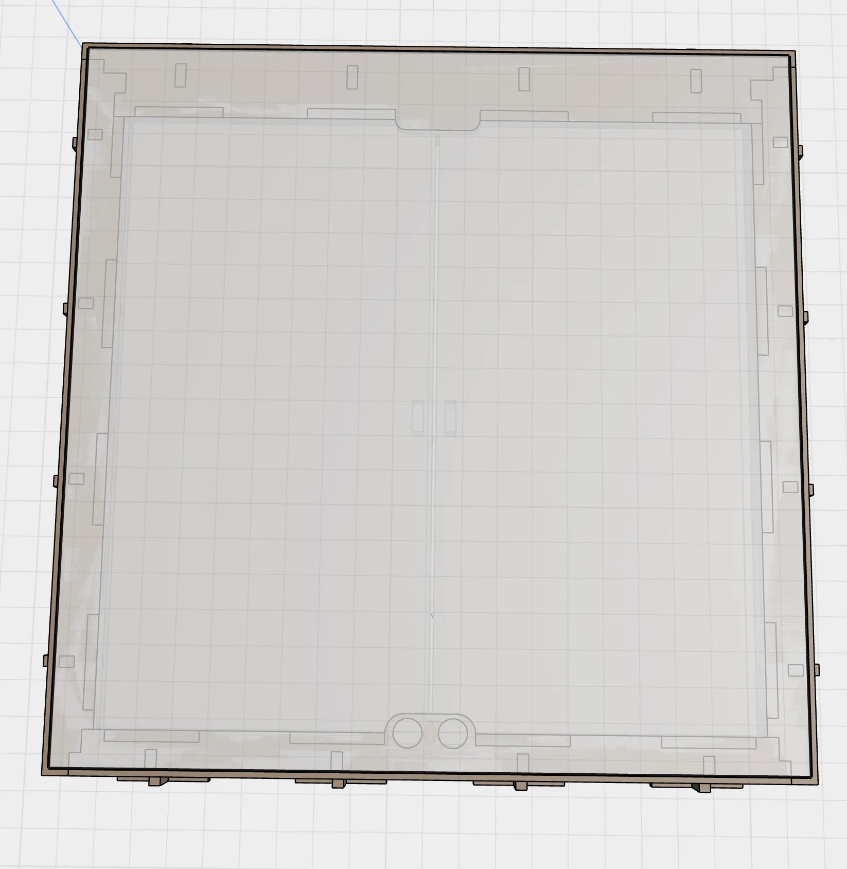
- Installation complete Ready for use
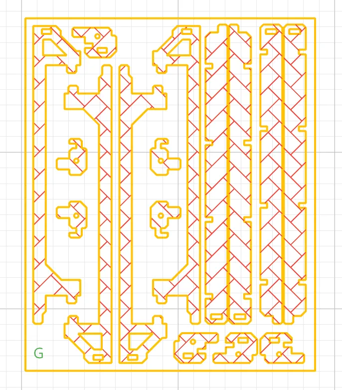
Locate the G-part plate, and prepare the top plate module, back plate module, left side plate module, right side plate module, and front frame module. Gather your materials: cotton swabs and your model.
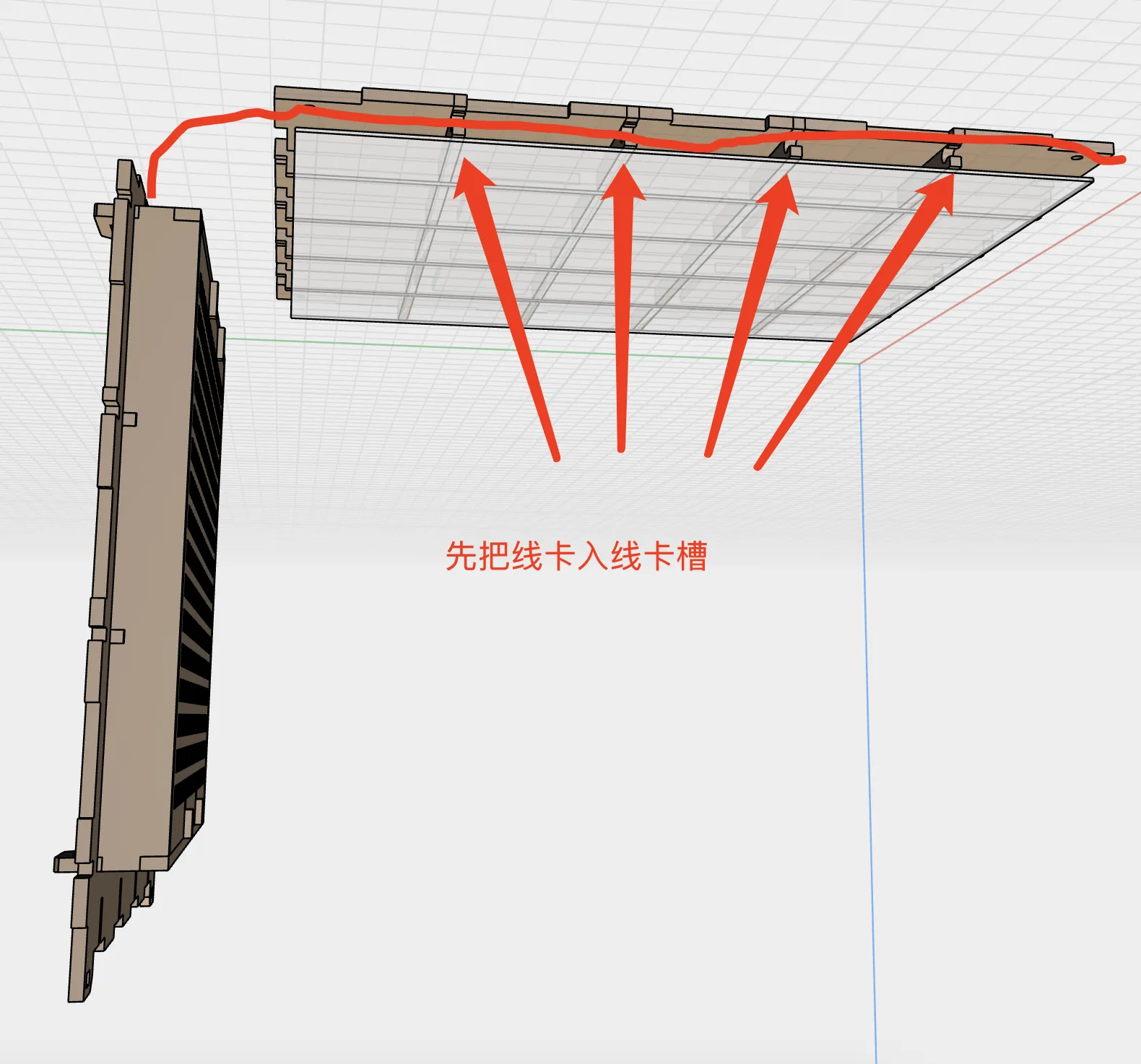
Assemble the top plate module and back plate module. First, insert the light cable into the cable slot, then combine the two modules.
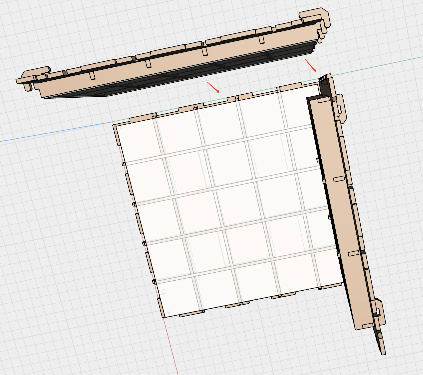
Next, assemble the left side module. Place the assembled modules on a surface and attach the left side module.
Take the upper left side strip, place it against the outer surface of the left side module, and slide it into place, aligning the strip's hole with the rear upper hole on the left side.
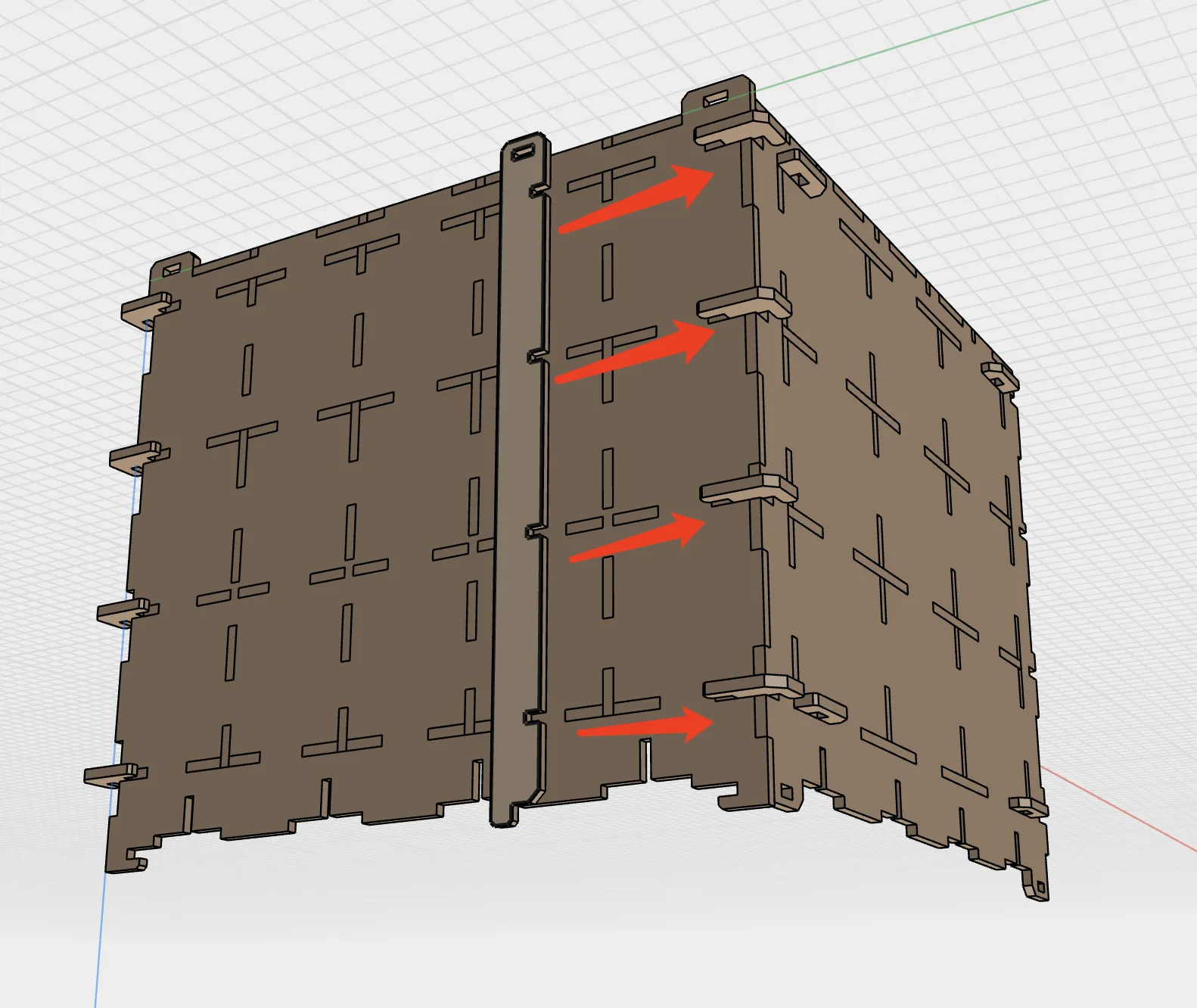
Take the upper left side strip, and insert it into the gap on the top left.
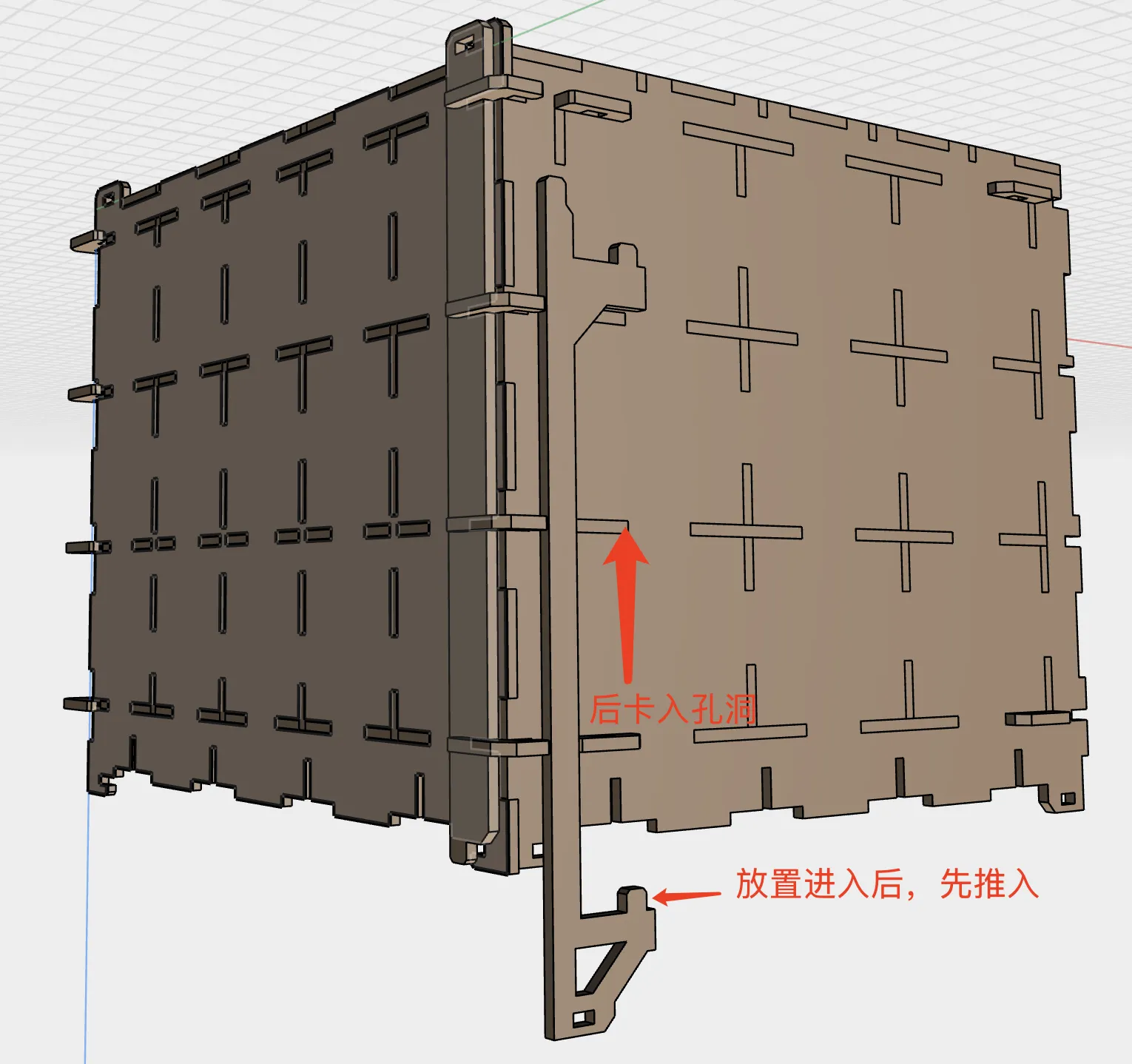
Take the locking latch, and slide it into the latch. A cotton swab may be used for insertion; leave approximately 3mm extending for easy removal.
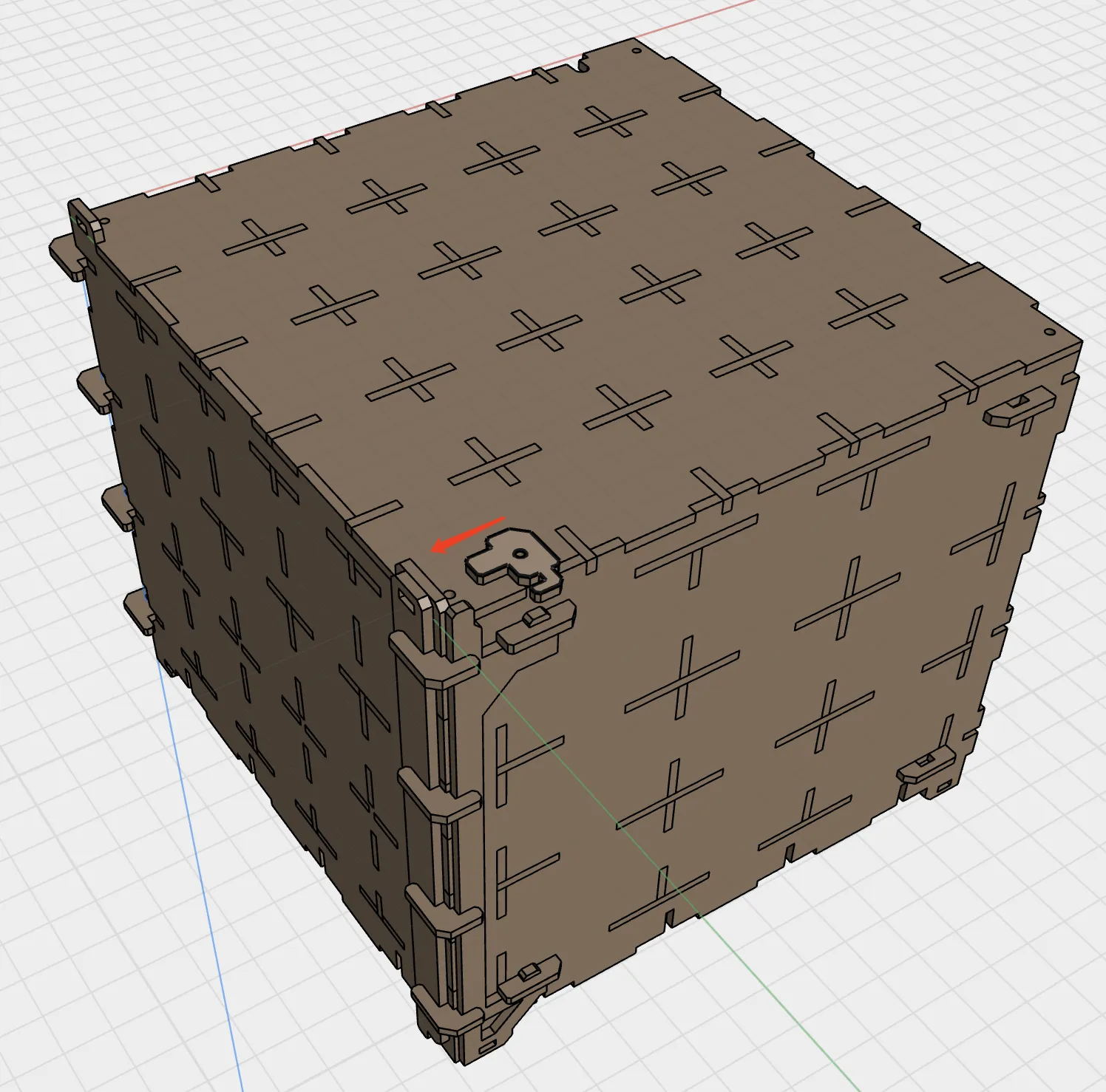
Repeat steps 3-6 to assemble the right side module. The completed assembly is shown below.
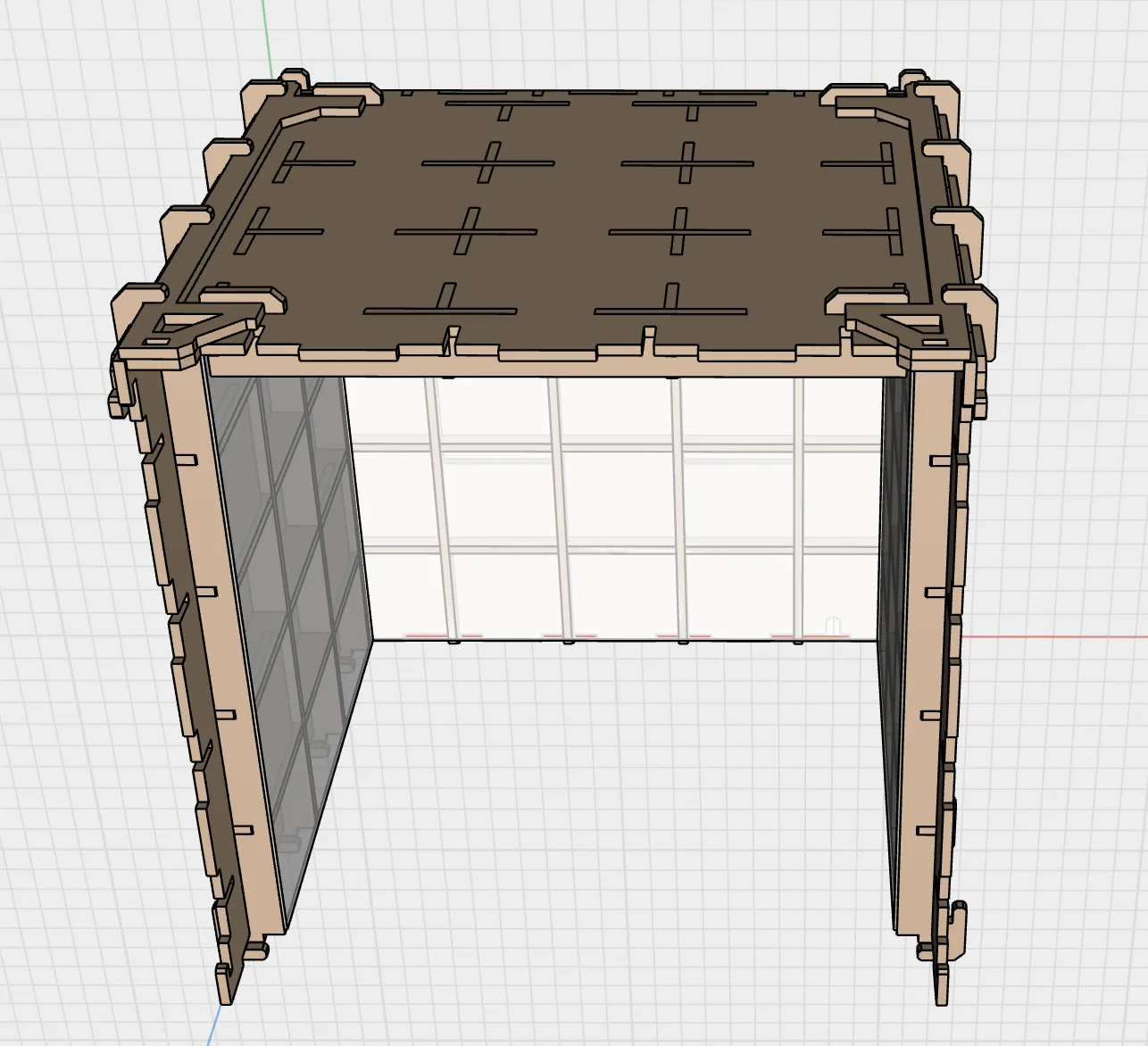
Assemble the bottom module.
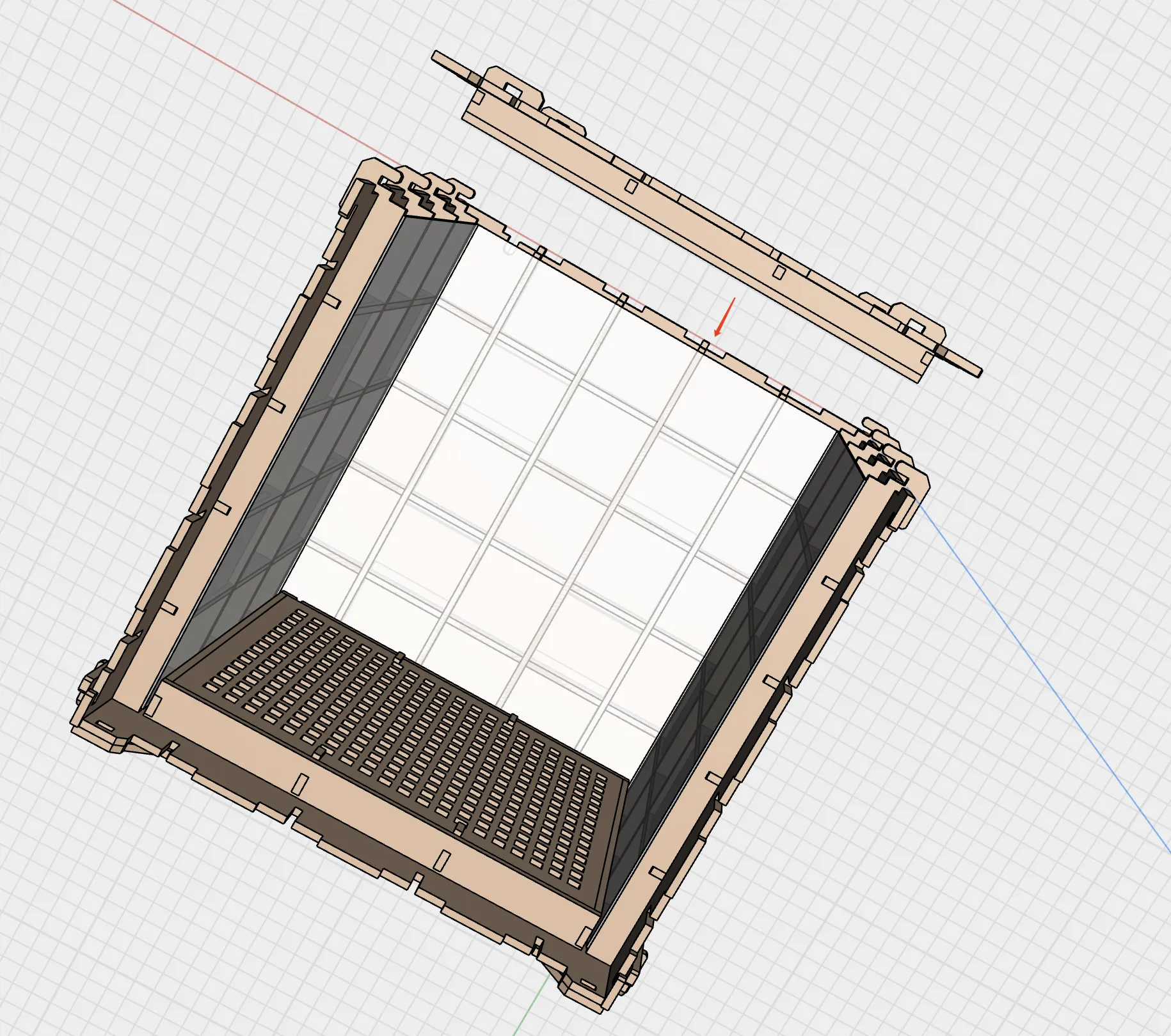
Take the remaining parts and install the side strips on the bottom module, following steps 4-6. Once installed, place the model in position.
(We recommend adhering the model to the base with an adhesive. Otherwise, the model may shift during handling, risking mirror damage.)
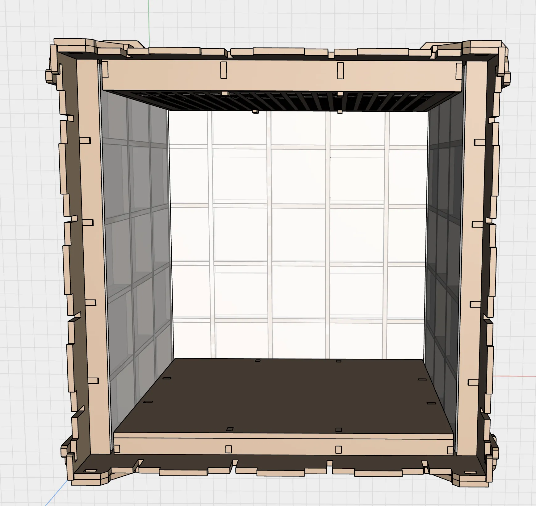
Insert the front frame module.
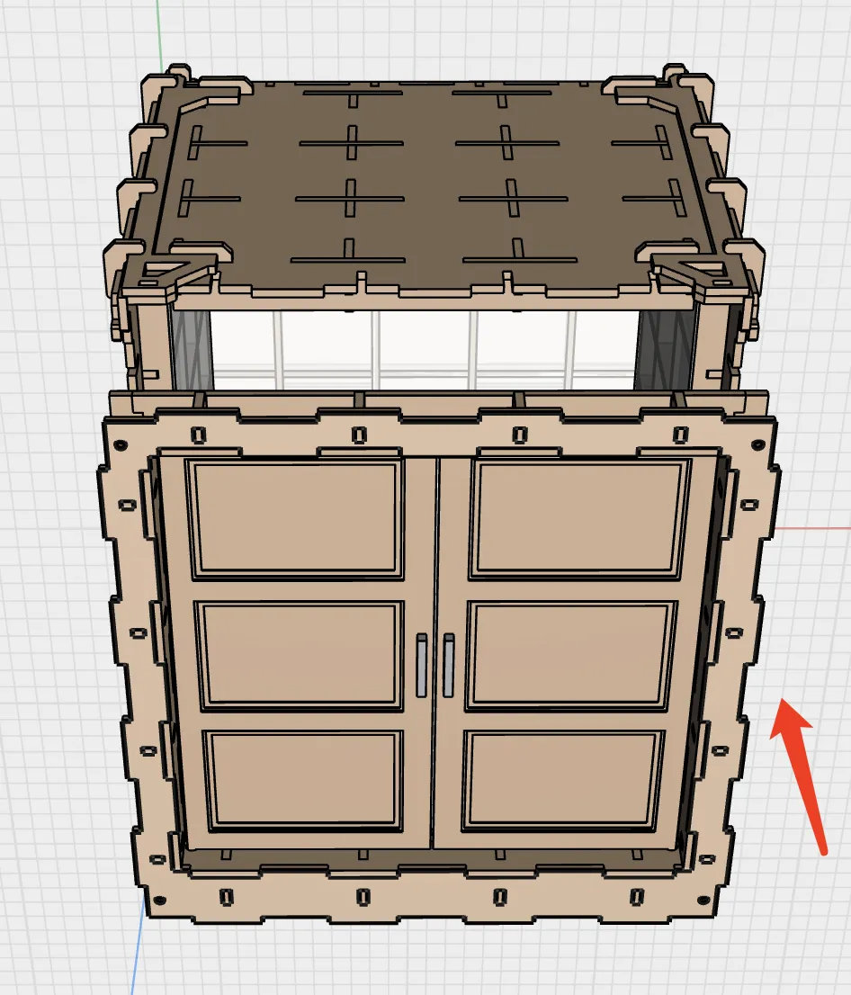
Finally, insert the latch accessory. Insert a cotton swab, leaving approximately 3mm extending for easy removal.
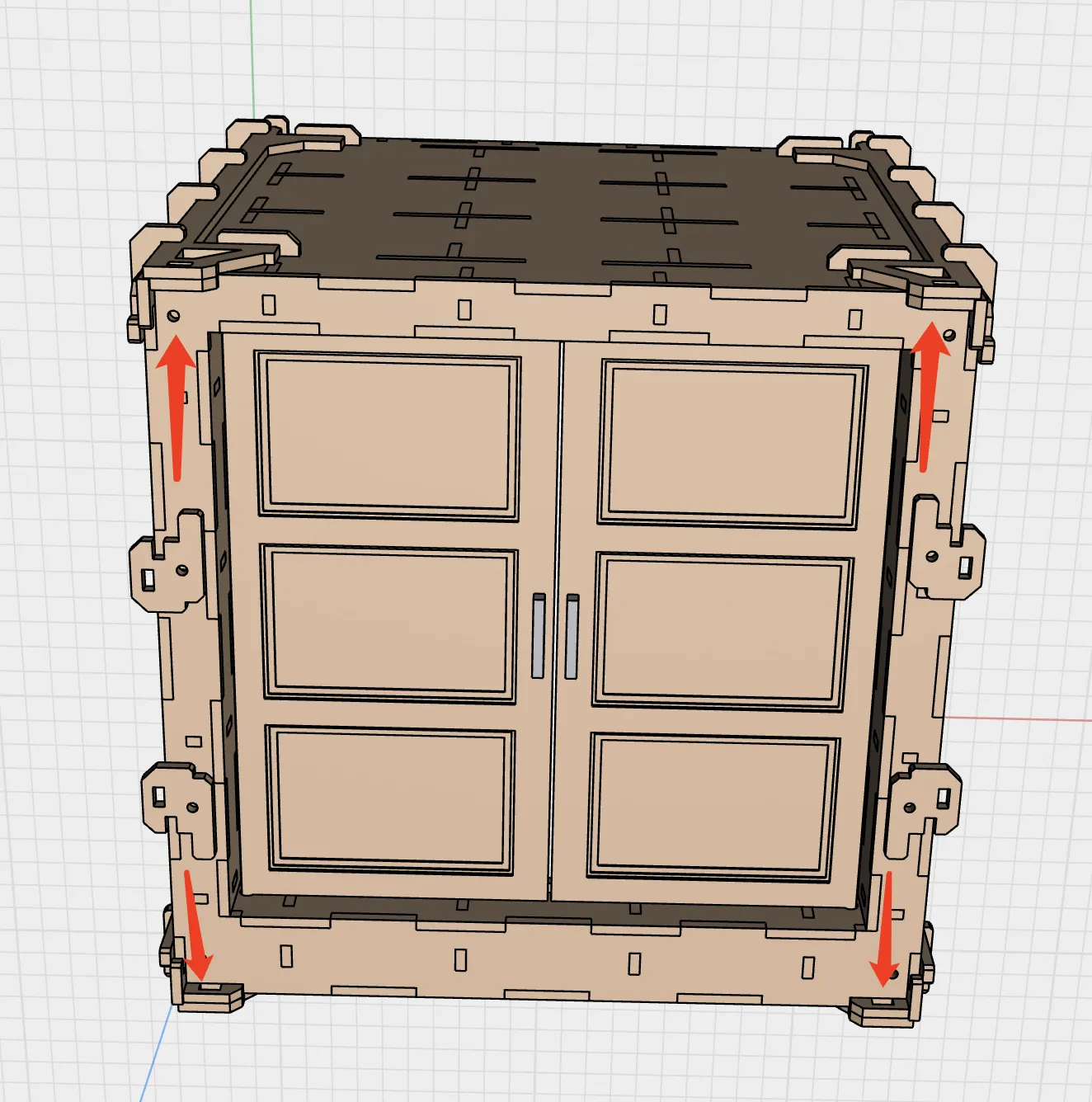
Documentation (1)
License

You shall not share, sub-license, sell, rent, host, transfer, or distribute in any way the digital or 3D printed versions of this object, nor any other derivative work of this object in its digital or physical format (including - but not limited to - remixes of this object, and hosting on other digital platforms). The objects may not be used without permission in any way whatsoever in which you charge money, or collect fees.
Comment & Rating (0)