Nintendo Switch Arcade NS Console Housing


Print Profile(4)


Bill of Materials

Description
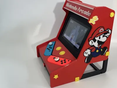
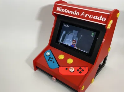
I dedicated nearly a week to crafting this Nintendo Switch NS arcade shell, meticulously testing each detail and ensuring charging port accessibility. I hope those who appreciate it will lend their support.
This design requires no metal components or supports—it's ready for direct printing.
Before printing, please confirm your PEI plate is impeccably clean. Applying adhesive, if necessary, can prevent printing failures, particularly with the smaller parts.
Note: The Nintendo Switch 2 is considerably larger, and lacking one myself, I cannot currently design for it.
All components are designed for PETG filament.
Feel free to leave comments regarding any printing issues.
Boost Me (for free)
Your support fuels my printing endeavors and the creation of new models, keeping this fan-made art freely available. Every contribution counts—thank you!

Detailed Assembly Instructions:
STEP 1: The main console components are shown below: |  |
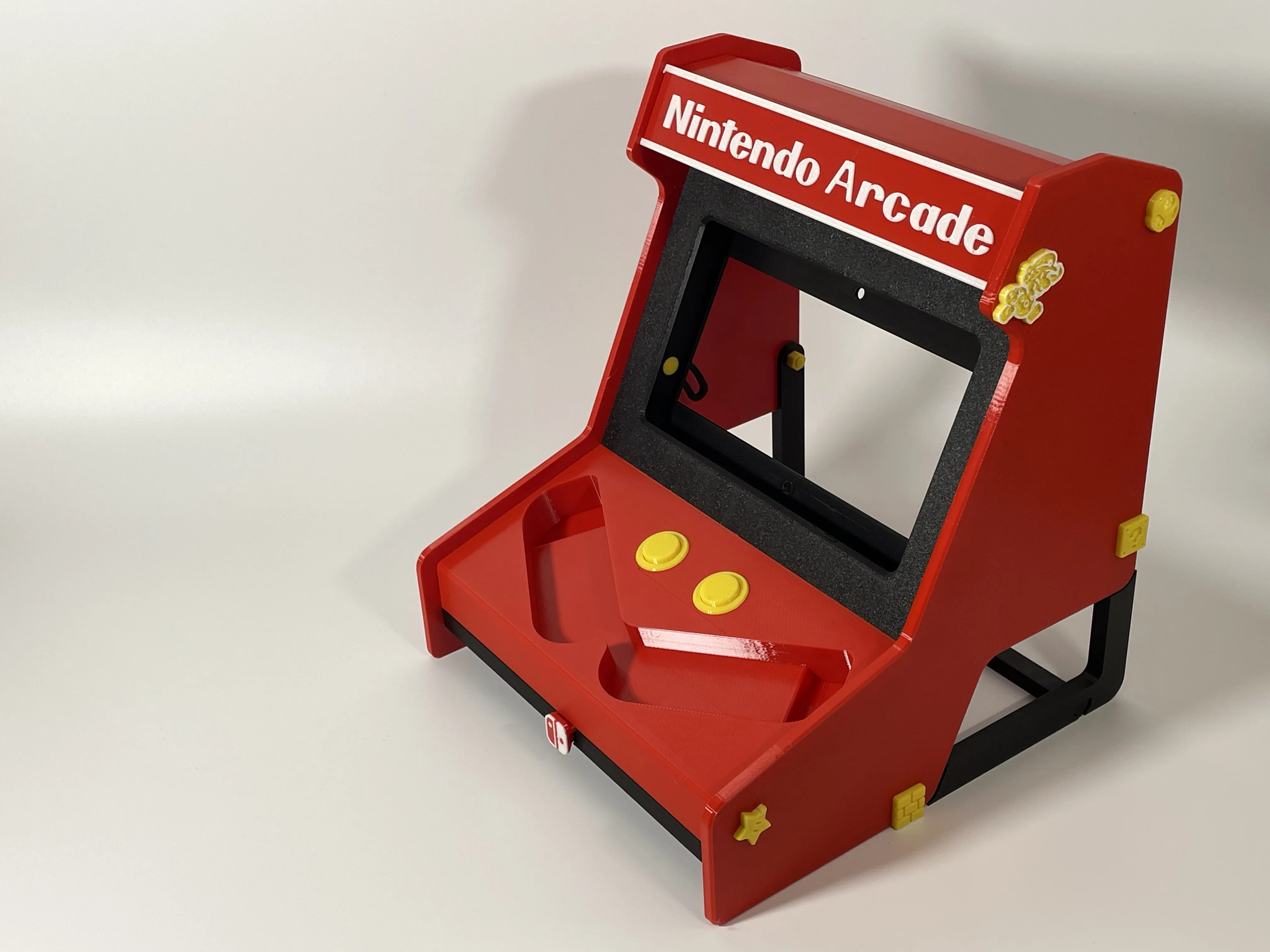
STEP 2: Install the controller base. First, insert the spring into the bottom of the button, then insert the button from the threaded side, and rotate the button into the base threads in reverse. The base installation is complete. |
   |
STEP 3: Install the front panel. Insert the clasps into the same positions on both sides of the front panel, prepare the flat-bottomed conical screws and 3mm thin nuts, and insert them into the holes on both sides. After aligning with the guide rails, tighten the screws to lock the guide rails. You can print an extra conical screw for the round hole in the horizontal bar at the back of the console to adjust the thickness. The slot is 16mm, and the console is approximately 13.9mm thick. Mine is with a shell, so the dimensions are perfect. |   
  |
STEP 4: Install the top cover letter plate. Press the two cylindrical clasps into the holes in the front plate and install them with the base plate. The cylinder can be scaled to control the size, used to clamp the panel, and the outer plate has a blank panel model for DIY letters. The holes in the panel can embed D5*2mm magnets to change panels more easily. Pay attention to the direction of the magnetic poles of the magnets. |    |
STEP 5: Insert the front panel into the base slot. | 
|
STEP 6: Align the controller base hole with the side plate protrusion and tighten the side plate threads with a long screw. |   |
STEP 7: Align the top cover hole with the positioning points, insert the front panel into the slot, and tighten the side plate with your preferred long screw and 5mm thick nut. |     |
STEP 8: Repeat the same method to install the other side panel. |
  
|
STEP 9: Install the stand and drawer. Insert the drawer handle through the clasp. Insert the stand crossbar into both sides of the upright base, align it with the side panel hole, and tighten it with a long screw. |
      |
STEP 10: Installation complete. |
 |


License
You shall not share, sub-license, sell, rent, host, transfer, or distribute in any way the digital or 3D printed versions of this object, nor any other derivative work of this object in its digital or physical format (including - but not limited to - remixes of this object, and hosting on other digital platforms). The objects may not be used without permission in any way whatsoever in which you charge money, or collect fees.
Comment & Rating (142)