
Pixel Clock Display
Print Profile(0)
Bill of Materials


Description
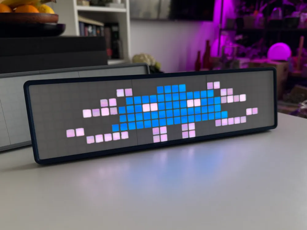
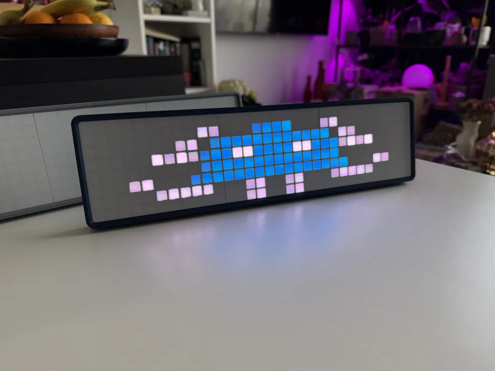
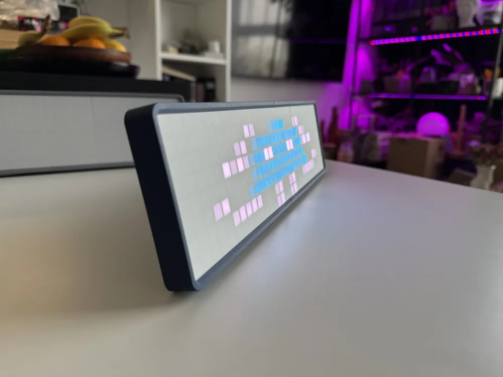
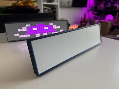
Pixel Clock Display
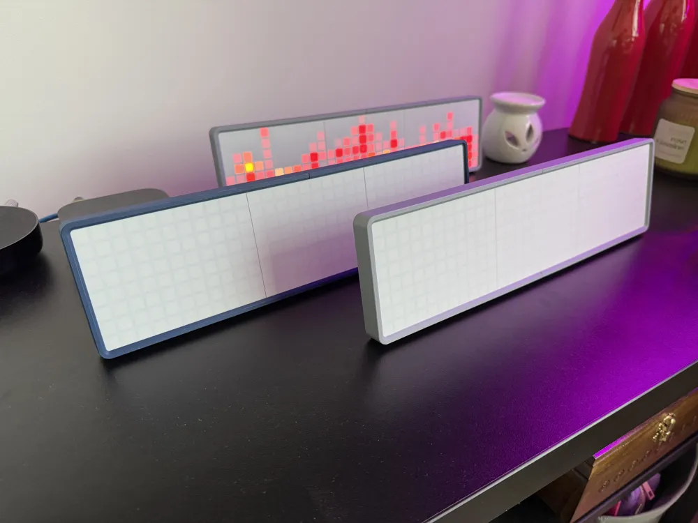
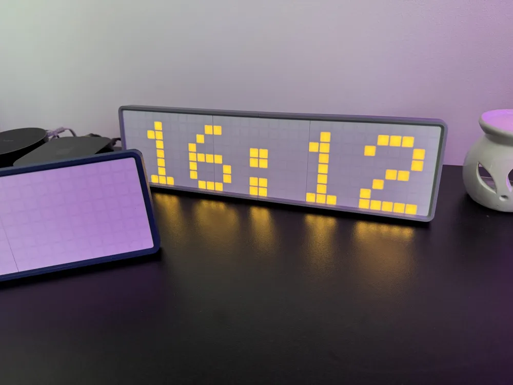
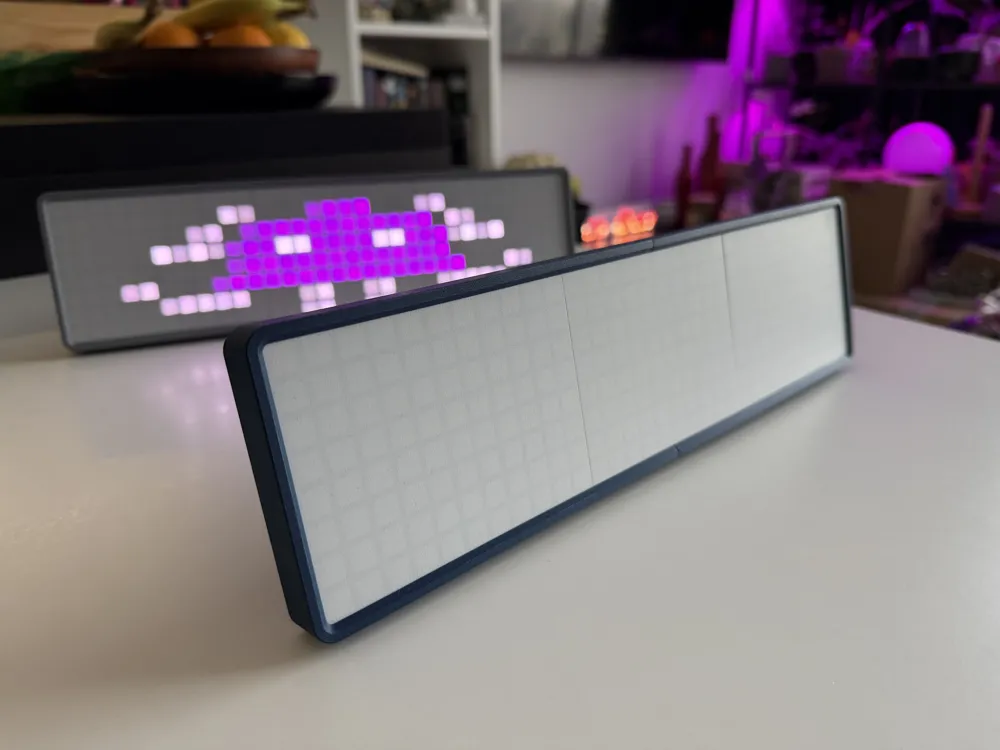
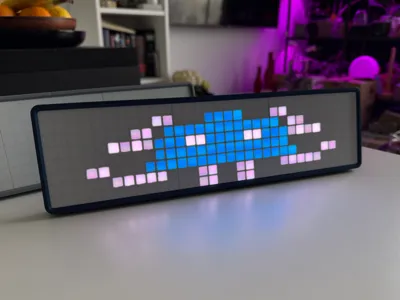
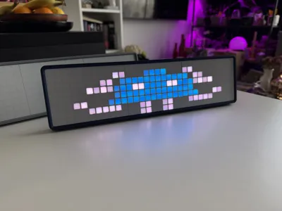
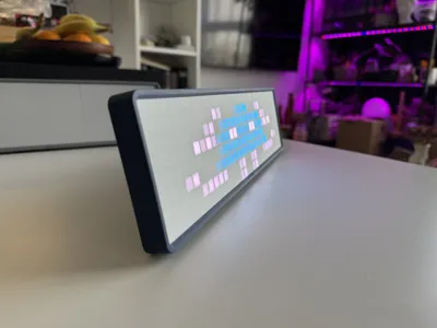
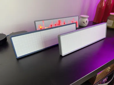
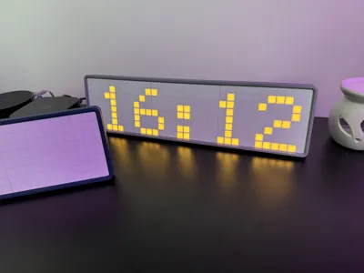
Easy to print, no supports, made to be seen.
Print all files preferably from listed below PLA Matte.
If You want best effect print grid first 2 layers from white filament and rest in grey.
This way grid should not be visible through white diffuser.
Grid is made from three parts You can print them all at once for fast printing.
If You want better quality print each part separately.
Provided files are STEP for better print quality (You need to dissasemble it in slicer) and 3mf already sliced with best settings in Orca Slicer.
All parts need to be glued. CA glue is sufficient.
First start by assembling diffuser grid together, smaller diffuser grid should be placed in the middle.
Arrange two bigger diffusers in a way where grid is touching walls are oriented toward smaller grid.
You can place printed parts over LED WS2812B Matrix Display for visual aid before gluing.
Second step is assembly of frame, glue it to the diffuser grid.
Be careful so glue will not go over small lip going over display diffuser.
Next step is to put LED Matrix Display inside glued together frame and grid.
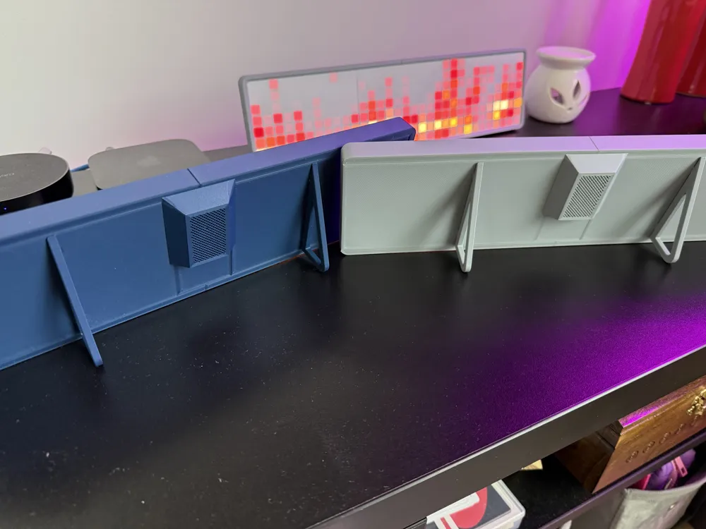
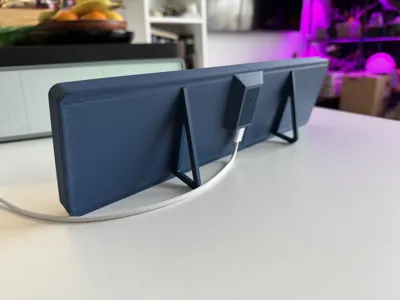
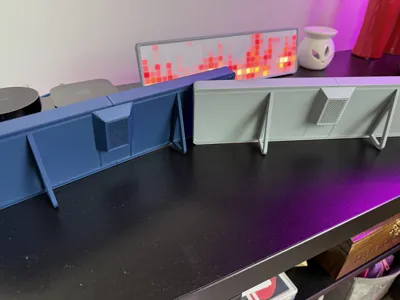
Back plate is printed out of 4 parts also needs to be assembled on flat surface.
Tolerances are tight for slide in with locking pin, You'll need to wiggle it a little.
Solder wire for data pin DIN and slide over the wire assembled backplate.
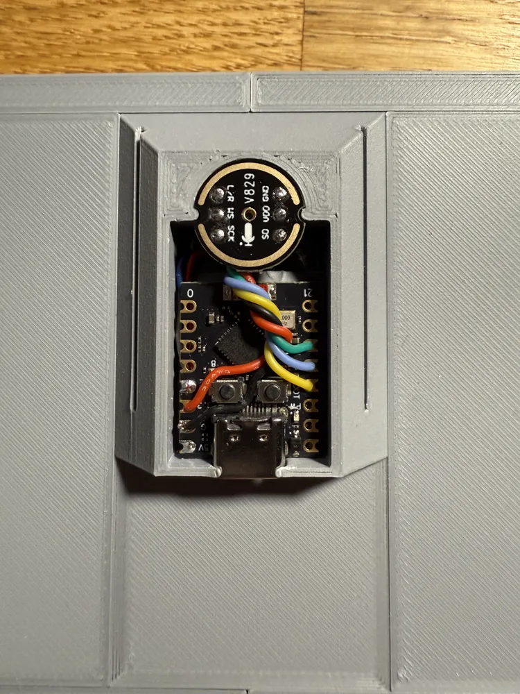
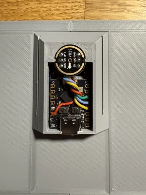
Through center hole You can take rest of data cable and solder it to ESP32-C3 super mini controller.
Rest of soldering needs to be done when back plate is in place eg. ground wire and power wire for 5V.
You'll need to be vigilant to not melt PLA with soldering iron.
ESP32 module is glued using VHB tape from 3M.
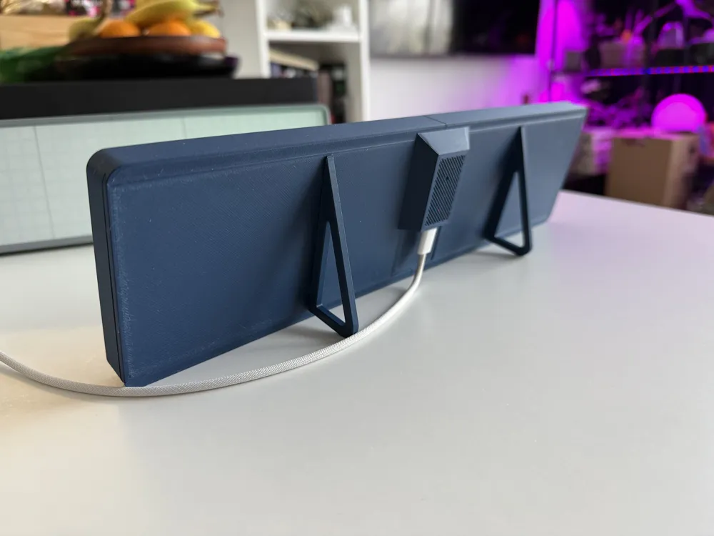
On the back there is place for digital microphone if You want display to be sound reactive.
Wiring and soldering scheme can be found on WLED Wiki: https://kno.wled.ge
Legs are press fitted but can be glued for security.
For powering use USB-C cable with short hub or angled one.
All needed parts are listed below.
Affiliate links, they are tested by me and are working.
If You'll like my design buy those parts from those links i'll earn small commission.
You can also support me by Boosting!
Boost Me (for free)
Why not?
I already have few ideas on V2.
Have Fun!
License



Comment & Rating (10)