
BlueDroid
Print Profile(0)
Description
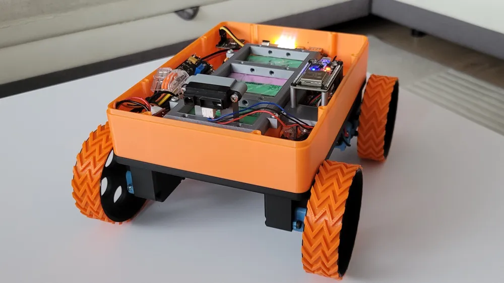
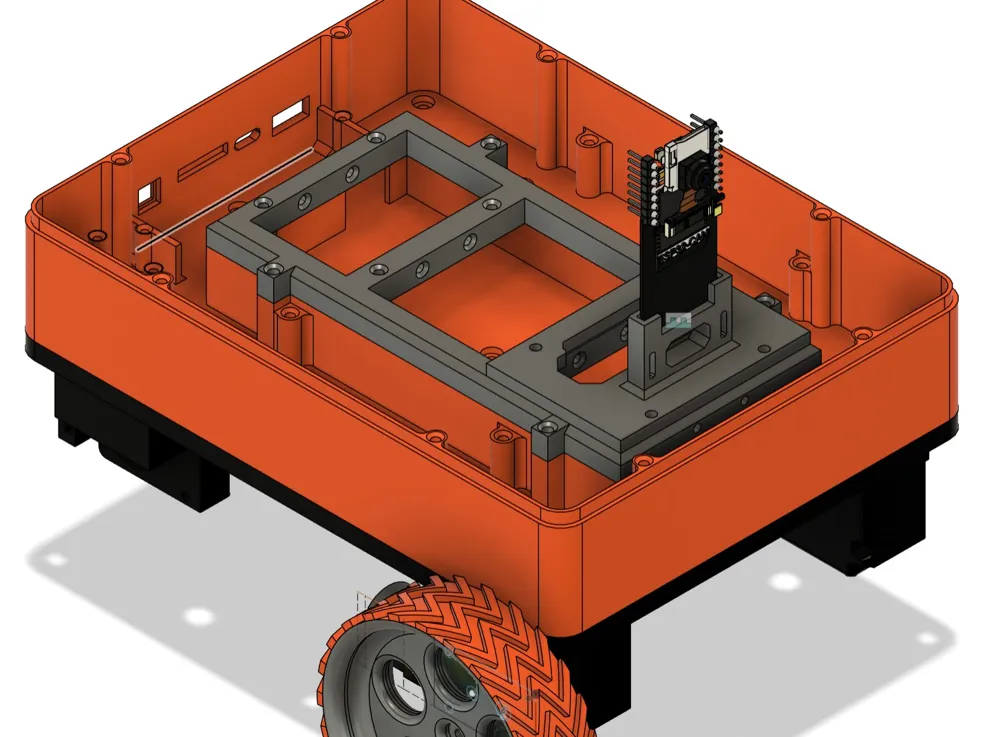
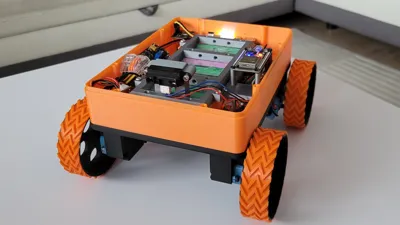
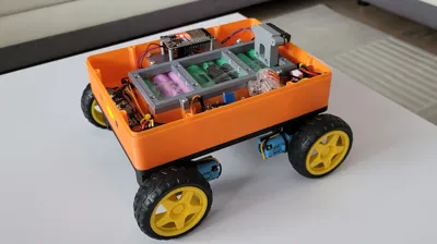
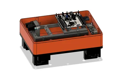
Modular 3D-Printed Robot – Description and Assembly Guide
This model has been designed for educational and experimental purposes related to microcontrollers, programming, and electronics. Its modular construction allows for easy expansion and adaptation to various applications.
Printing
It is recommended to print the components using PLA; however, other materials such as PET-G or ABS can also be used, allowing for experimentation with different mechanical properties.
The model's parts are precisely fitted. If your printer produces holes that are too small in the X-Y plane, it is recommended to use the "X-Y Hole Compensation" option (or a similar feature depending on your slicer) to adjust hole diameters and ensure proper fit.
If you decide to print the wheels, it is advisable to use TPU for the tires, which provides better grip and shock absorption.
Robot Modules
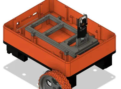
1. Chassis Module
The chassis supports:
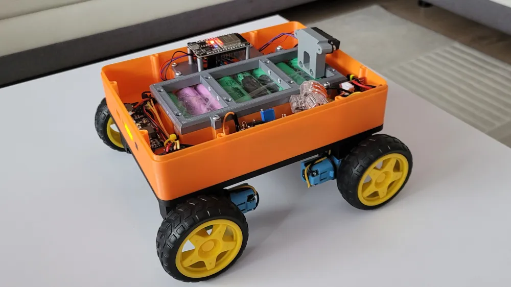
- Popular "yellow motors" with a 1:48 gearbox for standard wheels.
- Motors with a 1:90 gearbox designed for larger, 3D-printed wheels.
Motor Mounting:
- Each motor is secured with two M3 screws (40 mm long, preferably with flat heads) and one M3 screw (8 mm long).
- The motor can be reinforced in its mount by using a 608ZZ bearing and printing a shaft-to-bearing adapter.
2. Battery and Electronics Module
This module allows for the installation of:
- 18650 battery cells as a power source.
- Control electronics, including a PCB with the SW6106 chip (available on Aliexpress), which enables battery charging and provides a 5V supply for other components such as ESP32, Arduino, Nucleo, etc.
- A power button, allowing for convenient switching of the robot on and off.
- A module with the INA216 chip, which enables voltage and current measurement of the battery.
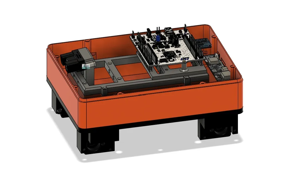
Electronics Adapters:
- Depending on the microcontroller used, special mounting adapters are available.
- Some adapters are directly screwed onto the battery module, while larger ones are attached to the battery cover.
Module Assembly
The chassis module is attached to the battery module using nine M3 screws (8 mm long, flat heads recommended, max. 2 mm).
Additionally, it is recommended to have a set of M3 and M2.5 screws and nuts in various lengths.
Electronics and Control
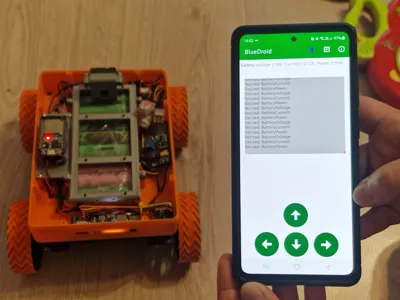
The robot shown in the images uses:
- The ESP-WROOM-32 development board (compatible with ESP32-DevKit).
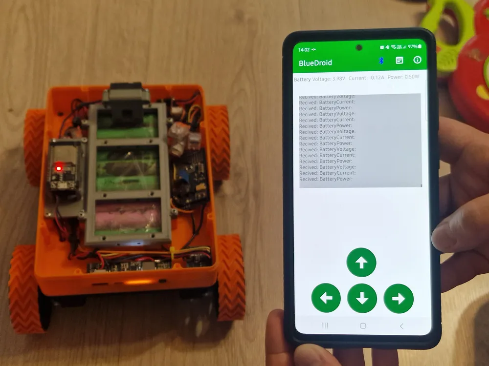
- A simple program written by me in the Arduino IDE, which allows the ESP32 to function as a Bluetooth Classic device in serial port mode (SPP), receiving text-based control commands from the BlueDroid app.
An example source code with explanations for the ESP32-WROOM-32 development board is available in the blueDroid.ino file. It serves as a working, very simple example of using this module.
This sketch is also available at:
GitHub - 8stone3/BlueDroid: BlueDroid - Firmware for Modular 3D-Printed Robot
Control App – BlueDroid
BlueDroid is a simple Android app developed by me that enables:
- Connecting to Bluetooth (SPP) devices.
- Sending simple text commands to control the robot's movement.
- Receiving feedback from the robot, such as power status.
The Android control app is available at:
https://www.exed.pl/BlueDroid/blueDroid.apk
License

Comment & Rating (1)