Search models, users, collections, and posts

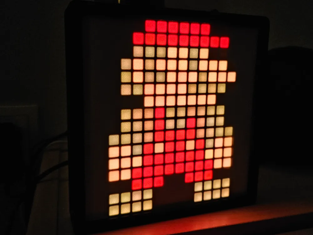
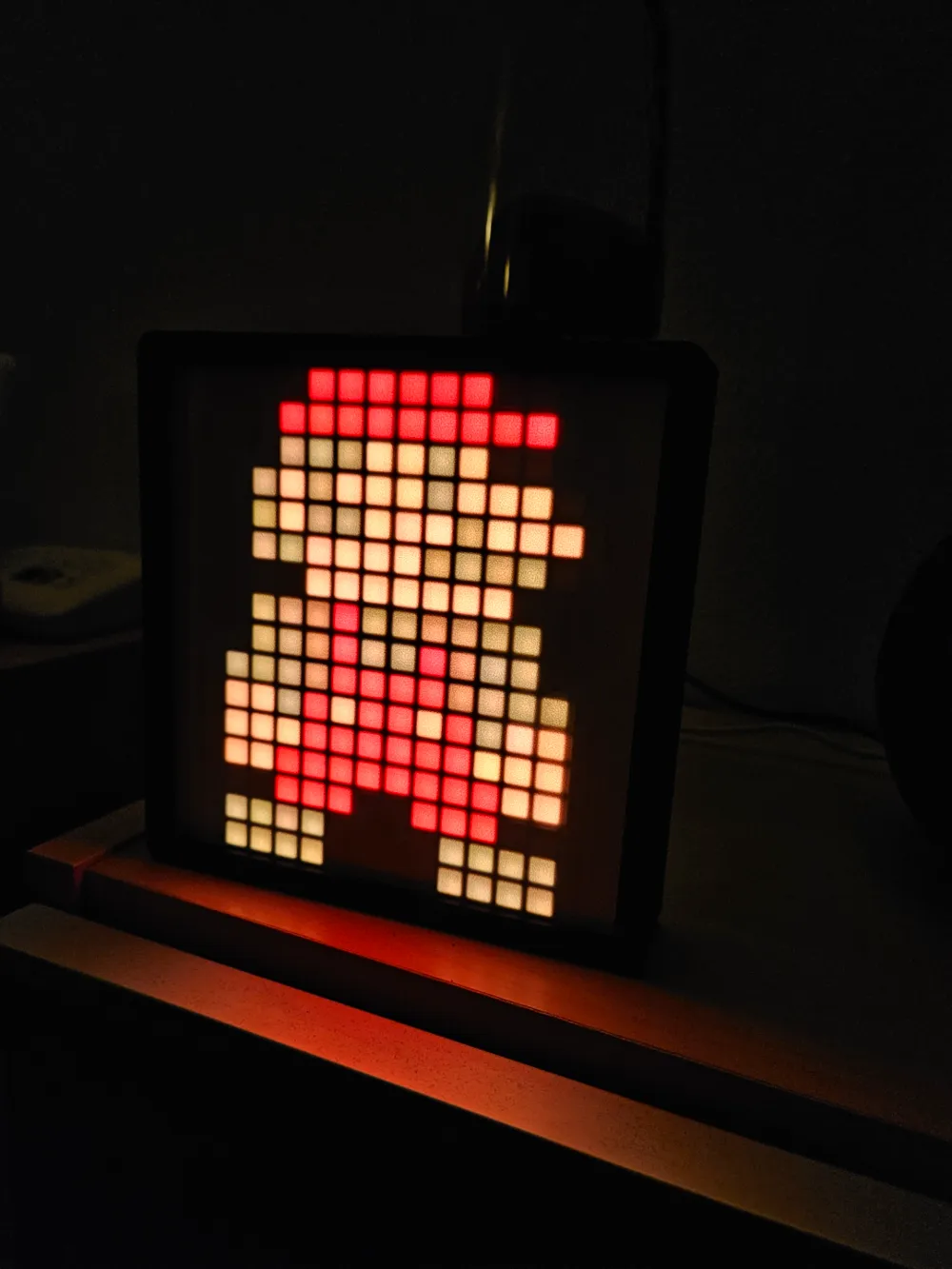
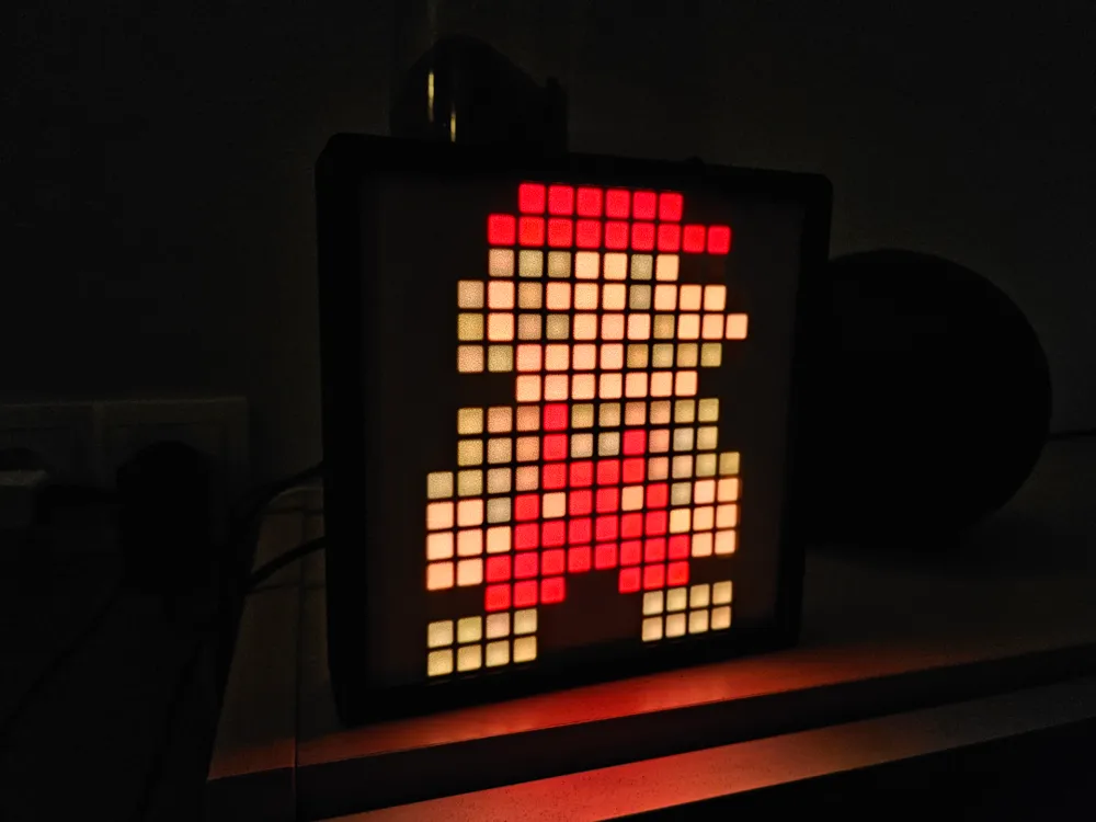
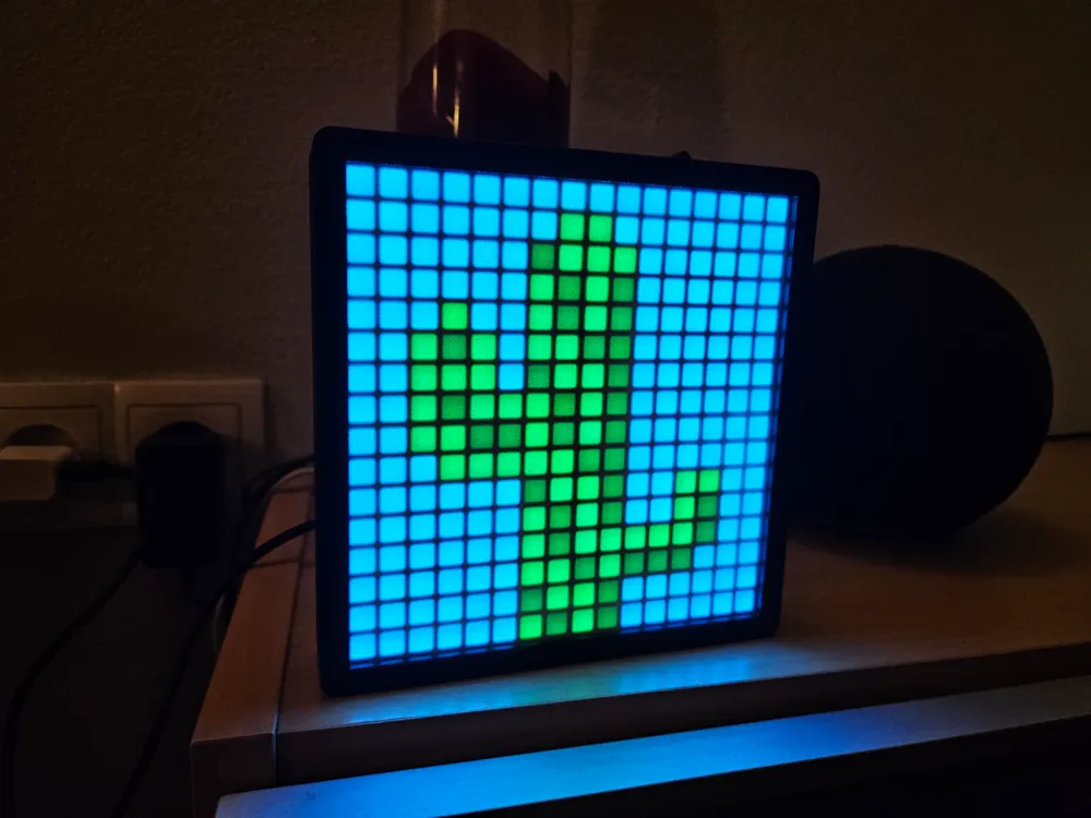
LED Matrix
IP Report
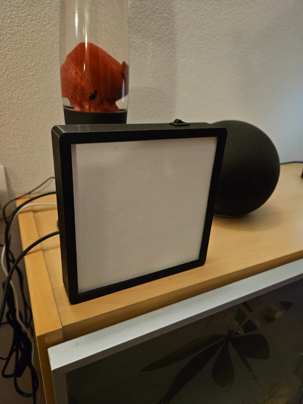
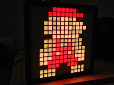
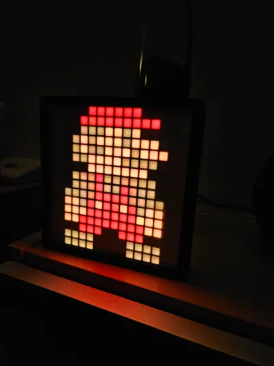
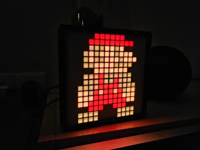
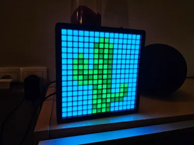
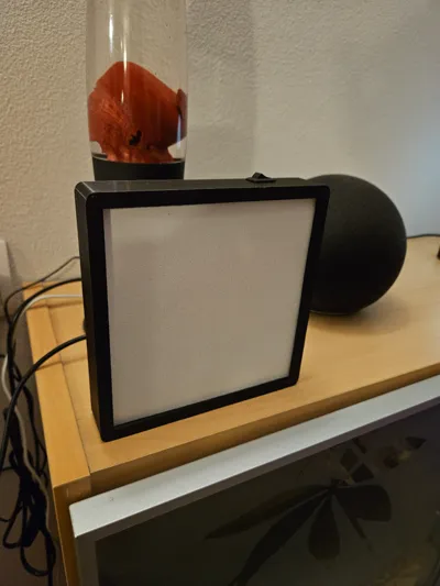
Print Profile(1)

0.16mm layer, 2 walls, 15% infill
Designer
7.3 h
5 plates
Open in Bambu Studio
Boost
45
131
6
6
91
29
Released
Bill of Materials
List other parts
- M1,7_Schrauben x 8:
- AWG20_Kabel x 3:
- USB-C_Board x 1:
- ESP8266_D1_Mini_Controller x 1:
- LED_Matrix x 4:
- AN/AUS_Schalter x 1:
Description
Content has been automatically translated.
The following links are not affiliate links, but they point to the components I used.
Components (electronic):
- Switch https://de.aliexpress.com/item/1005005325584703.html
- Cable (AWG 20 recommended) https://de.aliexpress.com/item/1005004167126040.html
- USB-C Board https://de.aliexpress.com/item/1005006221141627.html
- Screws (M1.7 – optionally M2) https://de.aliexpress.com/item/1005007345768217.html
- 4× WS2812 LED Matrix https://de.aliexpress.com/item/1005007398953448.html
- D1 mini Controller https://de.aliexpress.com/item/1005007877904928.html
This model is assembled in two main phases:
- Mechanical/Printed Phase:
– The individual parts are first created using 3D printing.
– This includes the grid, the front panel, and the housing, into which the electronics will later be integrated. - Electronic Phase:
– Once the printed parts are ready, the electronic components are assembled.
– First, the LED matrix modules are placed on the intended grid and secured using screws (M1.7 or M2).
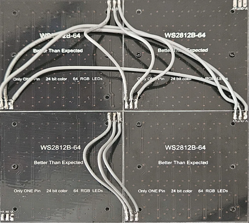
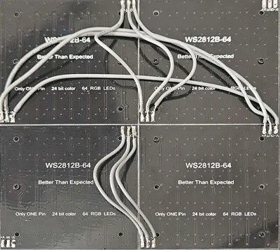
– Then, the matrix modules are soldered (see photo for reference).
– After that, cables are soldered to the controller (connections: 5 V, GND, D4), the power supply, and the switch.
Assembly Instructions (Electronics Integration)
Step 1: Mounting the LED Matrix
- Placement and Securing:
The four WS2812 LED matrices are placed on the designated grid and secured with the provided screws (M1.7). - Soldering:
Then, the matrices are soldered together and to the appropriate contact points (See reference photo).
Step 2: Wiring the Controller
- Controller Connections:
Solder the cables to the D1 mini controller. The following connections are necessary:- 5 V
- GND
- D4 (data line for LED matrix)
- Power Supply & Switch:
- The first 5 V cable from the USB-C port (i.e., the power source) is soldered to one end of the switch.
- The other side of the switch is connected to the cable coming from the 5 V connection of the D1 mini and the + cable of the matrix.
- Note: Optionally use heat-shrink tubing for insulation and improved stability.
- Data Cable:
Solder a cable between the input of the LED matrix (LED Matrix IN) and the controller connection D4. - Ground Connections:
All ground wires – the cable from the USB-C power supply, the cable from the matrix (already soldered to –), and the one from the controller (GND) – are connected together.
Step 3: Assembling the Housing
- Front Panel and Grid:
After the electronic connections are made, the front panel of the model is clipped onto the grid. - Installation in the Housing:
The entire assembly is inserted into the provided housing.
The individual components (switch, USB-C board, etc.) are mounted in their designated openings. - USB-C Board Securing:
It may be necessary to pre-fix the USB-C board with super glue to ensure a stable connection.
Setting up the D1 mini and Installing WLED
To make the model “smart,” the D1 mini controller is equipped with the WLED firmware. Here’s how:
1. Preparation
- Connection to PC:
Connect the D1 mini to your PC via a USB cable.
2. Flashing the Firmware
- Using the Flash Tool:
Use https://install.wled.me to transfer the firmware to the D1 mini. - First Start:
After flashing, the D1 mini starts, and configuration can begin.
3. Setting up the WLAN Connection
- Configuring WLAN:
Connect to the WLED AP (using your smartphone or PC) and open the address http://4.3.2.1/ or http://wled.local/ in your browser.
Enter your WLAN credentials here so that the D1 mini connects to your home network.
4. Configuring the LED Matrix in WLED
- Accessing the Web Interface:
After successful WLAN setup, you will find the IP address of your D1 mini in your router or via the WLED app. - Making Settings:
- In the WLED web interface, go to LED Preferences and select the total number of LEDs (here 256).
- Go to the settings and under 2D Configuration select “2d Matrix” and save.
- If necessary, adjust other parameters such as brightness and layout (matrix layout, sequence) so that your 16x16 LED array is displayed correctly.
- Saving & Testing:
Save the settings and test if the LED matrix reacts as desired.
5. Final Assembly
- Once functionality is confirmed, the D1 mini is slid into the designated opening on the back of the housing, and the housing is closed.
License

This user content is licensed under a Standard Digital File License.
You shall not share, sub-license, sell, rent, host, transfer, or distribute in any way the digital or 3D printed versions of this object, nor any other derivative work of this object in its digital or physical format (including - but not limited to - remixes of this object, and hosting on other digital platforms). The objects may not be used without permission in any way whatsoever in which you charge money, or collect fees.


Comment & Rating (6)