Mini Turbojet Engine | Adjustable Nozzle


Print Profile(2)


Description
Membership
Want to support me or sell my models? Join here!
!!! MAKE SURE YOUR PRINTER IS CALIBRATED AND BED CLEANED, OTHERWISE PARTS MAY NOT PRINT CORRECTLY BECAUSE OF SMALL SIZE !!!
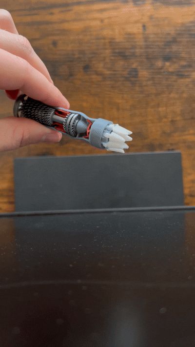
It spins and nozzle is adjustable! Fits in the palm of an average sized hand and prints in just over an hour if all printed on the same plate.
About :
This is a SUPER simplified version of a turbojet engine, it features the diffuser, compressor stages, Combustion stage, High pressure turbine, low pressure turbines, afterburner, and adjustable nozzle. The low pressure turbines spin with the fan, while the compressor spins seperatly if chosen to glue.
TurboProp here!
Printing:
Supports are needed and the standard tree supports work. Just make sure to uncheck these options.

Assembly Instructions:
- No hardware needed, just tweezers for assembly.
- Super glue is optional, but recommended especially for afterburner and fins of the nozzle.
- It doesn't need superglue to stay together if it just sits, but the afterburner is quite delicate.
Step 1: Make sure you have all the peices

The parts for the first step are in the picture below, and the fans will be placed in this order.

The flat side of the compressor fan will be facing the nub on the shaft.
If you want to glue together the high pressure compressure and turbine, this is a good time to do so and is shown below, it will be all of the circle hole parts.

The final result of step one should look like this.

Step 2:

Parts for this step above.
Insert the shaft into the cone on the exit side of the engine,
then place the diffuser onto the entrance side of the shaft
and press the diffuser into the body. Result is below.

Step 3:

First place the first burning stage in between the compressor and turbine stages.
It rotates into place, with the two notches lined up.
This part is tidious, tweezers are verrryyyyyy helpful. Put a dab of glue onto each leg.
Place the Afterburner into place, the three legs place into 3 notches in the housing.
Results below.


Step 4:

Place the nozzle adjuster onto the housing as such, Line up the extrusion into the notch as shown below.

Step 5:

This part can also be tricky, the skinny parts of the fins could bend, so be careful.
The skinny part slides into the notches beneath the holes,
You can choose to put superglue in the holes so that the fins won't come out.
The fins should slide in about as much as shown below.

Step 6:
Your done!!
The nozzle can be adjusted by pushing and pulling the piece over the fins. There is a notch in the housing that fits that extrusion from before that it rotates and clips into.The picture below shows the flared setting. The is a video in the pictures above.

Thanks for downloading and hope you enjoy!
Boost Me (for free)
Help support me in my future designs, Thanks!
License
You shall not share, sub-license, sell, rent, host, transfer, or distribute in any way the digital or 3D printed versions of this object, nor any other derivative work of this object in its digital or physical format (including - but not limited to - remixes of this object, and hosting on other digital platforms). The objects may not be used without permission in any way whatsoever in which you charge money, or collect fees.
Comment & Rating (85)