
Axial Flux Alternator
Print Profile(1)

Description
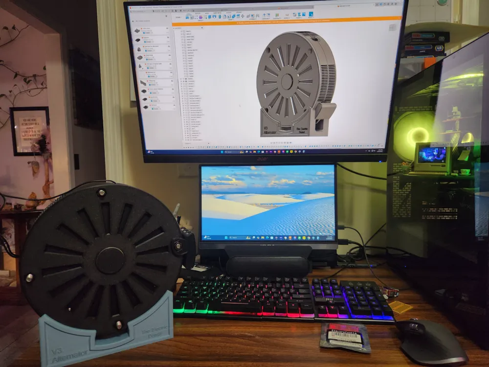
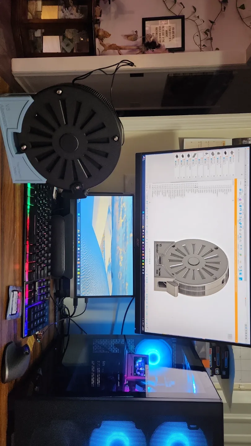
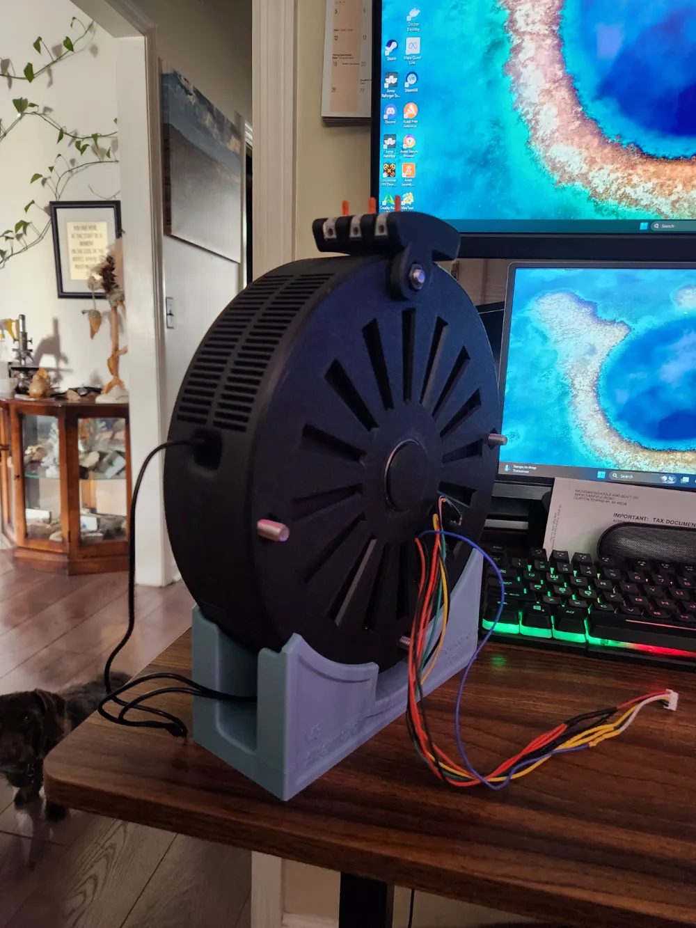
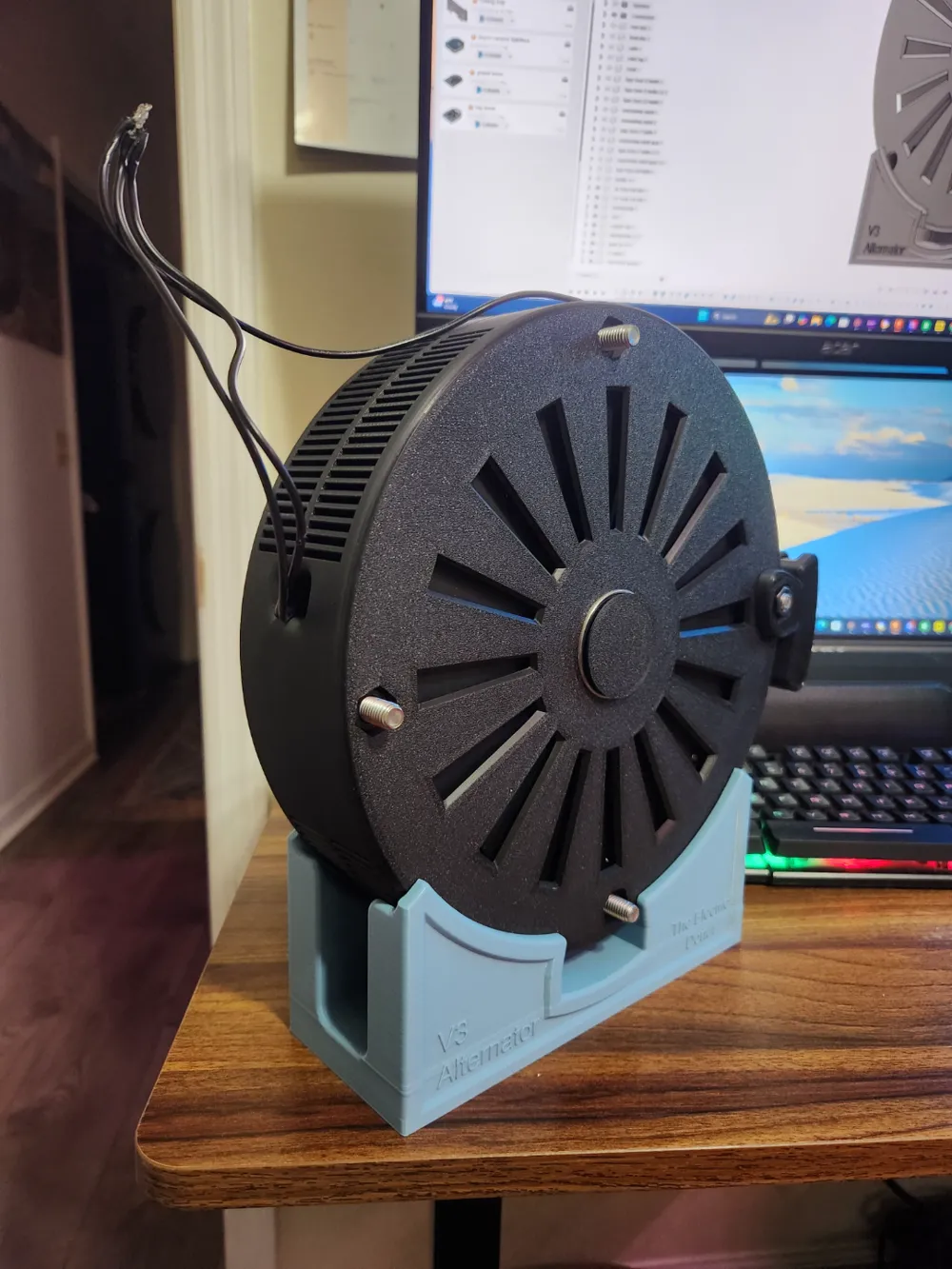


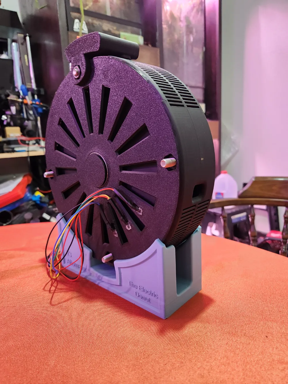
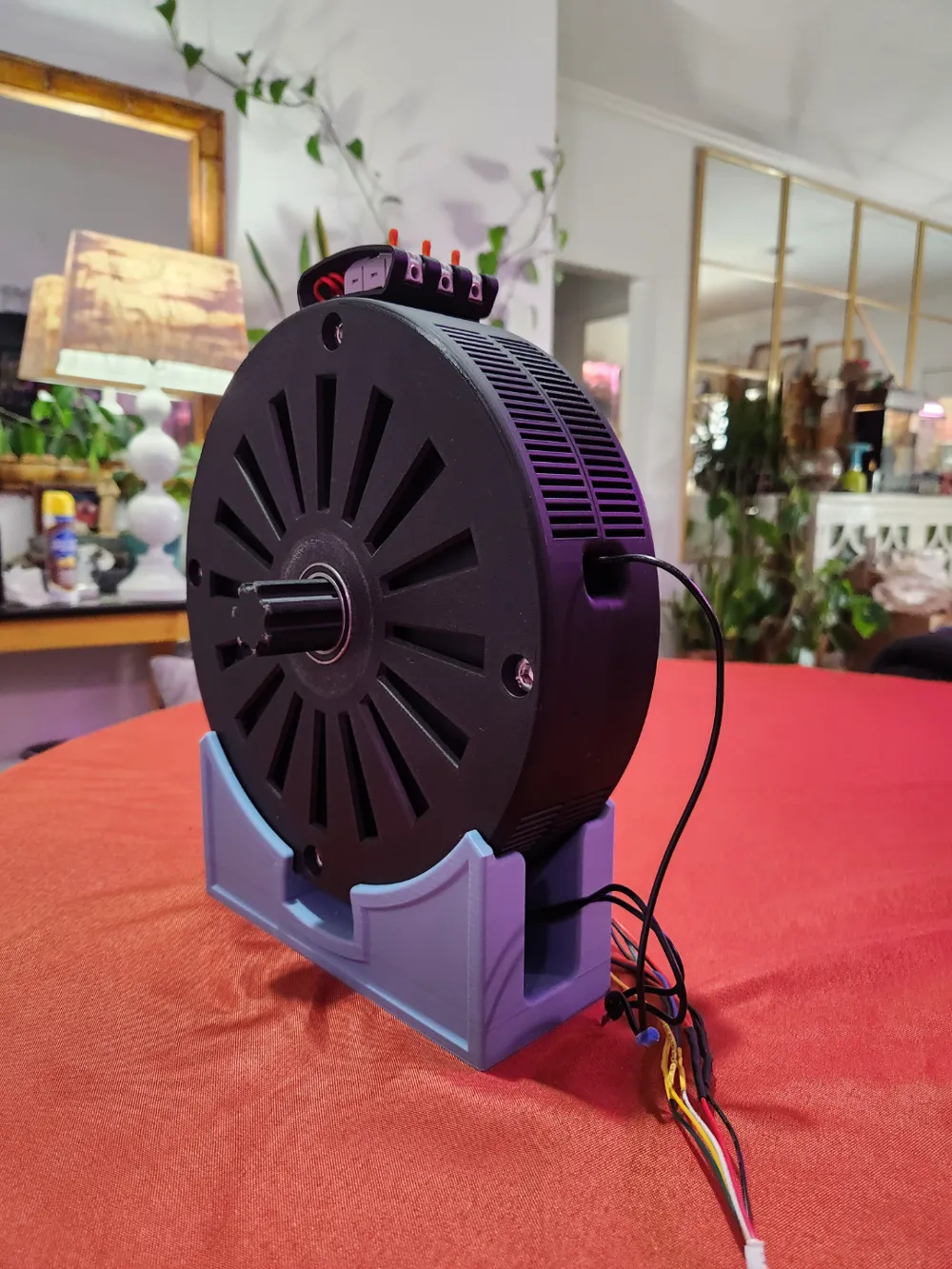
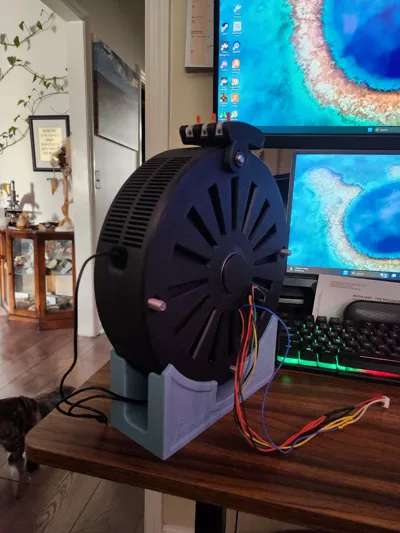
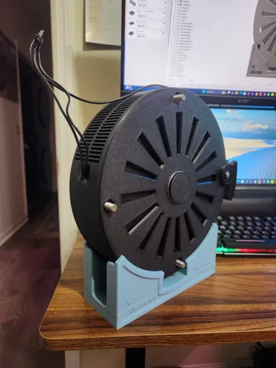
Axial Flux Alternator – 9 Coils, 12 Poles, Dual Rotor (Educational Model)
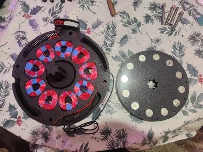
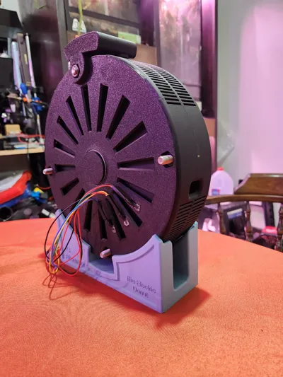
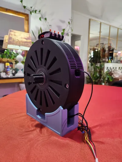
Unlock the potential of axial flux alternators with this 9-coil, 12-pole dual-rotor design! Designed for learning and experimentation, this alternator provides hands-on experience with electromagnetic power generation. Whether you're an engineer, student, or DIY enthusiast, this model serves as an excellent educational tool.
Add-Ons (this list will keep growing so come back and check out new features for this alternator)
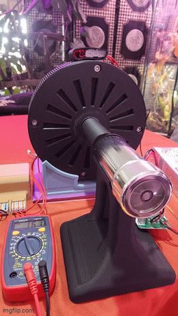
- Overrunning clutch: Check it out!
- Dual stage 1:4 Gear box for A-F: Check it out!
Key Features:
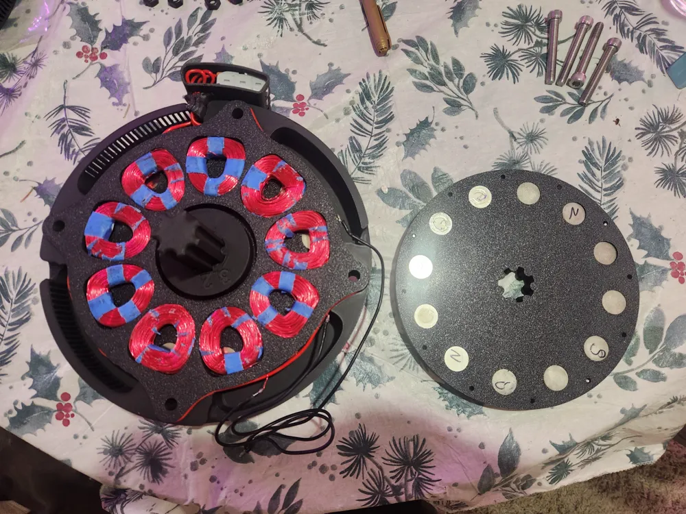
Dual Rotor, 12-Pole Configuration – Magnetic fields pass through the stator for efficient induction.
9-Coil Stator – Optimized coil arrangement to demonstrate power generation principles.
Adjustable Magnet Setup – Each pole can hold up to four 30mm × 2mm N52 neodymium disc magnets, but spacers are included for those who prefer fewer magnets per pole.
Modular & Expandable – Some parts are swappable, and future versions will introduce new configurations and components.
Material List:
-72x Neodymium Disc Magnets (N52, 30mm × 2mm) – Creates alternating magnetic fields. Buy Here
-Enameled Copper Wire (16GA, 18GA, 20GA) – Used for winding coils. Buy Here
-4x M8 Socket Head Bolts (60mm) – Secures rotor and stator assembly. Buy Here
-4x M8 Nuts – Locks the assembly in place. Buy Here
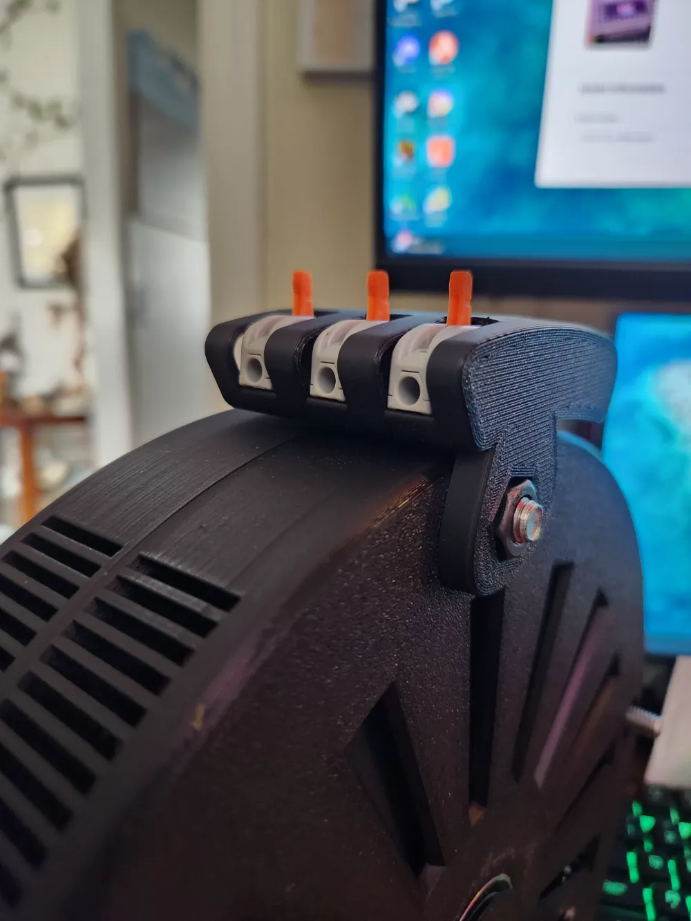
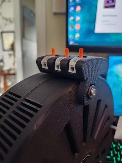
-HTCELLE 60pcs Wire Connectors (Optional) – Ensures reliable electrical connections. Buy Here
-16-20GA Red & Black Wire – Power transmission lines. Buy Here
-Hall Effect Sensor (Optional) – Measures magnetic field strength and position. Buy Here
-Speed Controller (Optional) – Regulates rotational speed. Buy Here
-Multimeter (Optional) – For testing voltage, current, and resistance. [Link]
-3-Phase Rectifier – Converts AC output to DC. Buy Here
-40x M3 Threaded Inserts – Provides secure mounting points. Buy Here
-40x M3 5mm Screws – Fastening components together. Buy Here
-2x Bearings (30mm ID, 42mm OD) – Ensures smooth rotor movement. Buy Here
Example Coil Winding Information:
-Voltage & Current Output – Varies based on RPM, wire gauge, and turns per coil.
-Coil Wraps – Typically 20-50 turns per coil, with higher turns increasing voltage output.
Wire Guide:
-16 AWG – Handles ~10A, low resistance for high-current applications.
-18 AWG – Supports ~7A, balancing current capacity and ease of winding.
-20 AWG – Supports ~5A, ideal for lower-power experimental setups.
Future Upgrades & Modular Design:
This is just the first version! Future models will include:
Different coil and pole configurations for varying power outputs.
Alternate magnet arrangements to explore performance changes.
New modular components that allow users to easily swap out parts for customization.
Buy Here:
Get everything you need to build your axial flux alternator using the links in the materials list above!
Stay tuned for new versions and add-ons to expand your learning and experimentation opportunities!
P.S.
If anyone needs help feel free to reach out in the comments. I will gladly share my knowledge of what i have learned. I love critiques and concerns as well; Im trying to make this as easy of an educational model as possible! Thank you and i hope you enjoy!
Also my coils in the picture are way to big follow the 20-50 turns for 12-16awg and lean more to 40-100 turns for 18-24awg. Feed back on the new coil cases would be great seem to be easier then the free floating coils.
License



Comment & Rating (9)