
Motorized Hands Free Turn Table
Print Profile(1)

Description
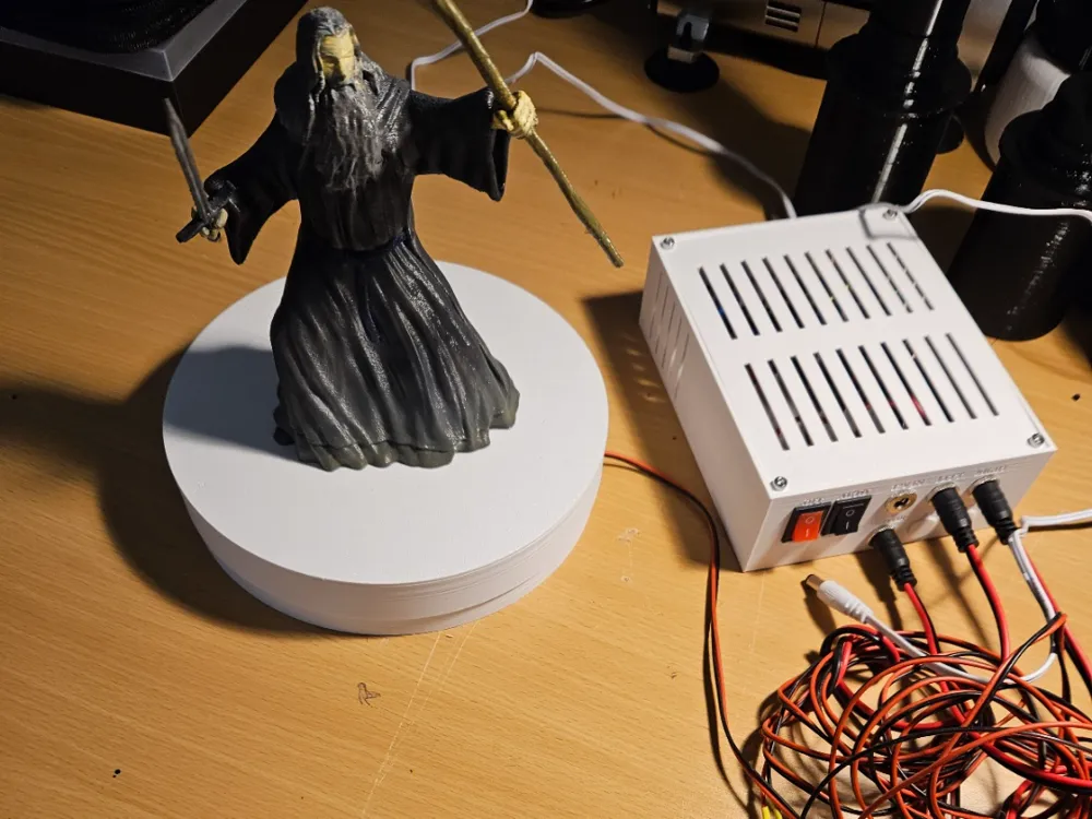
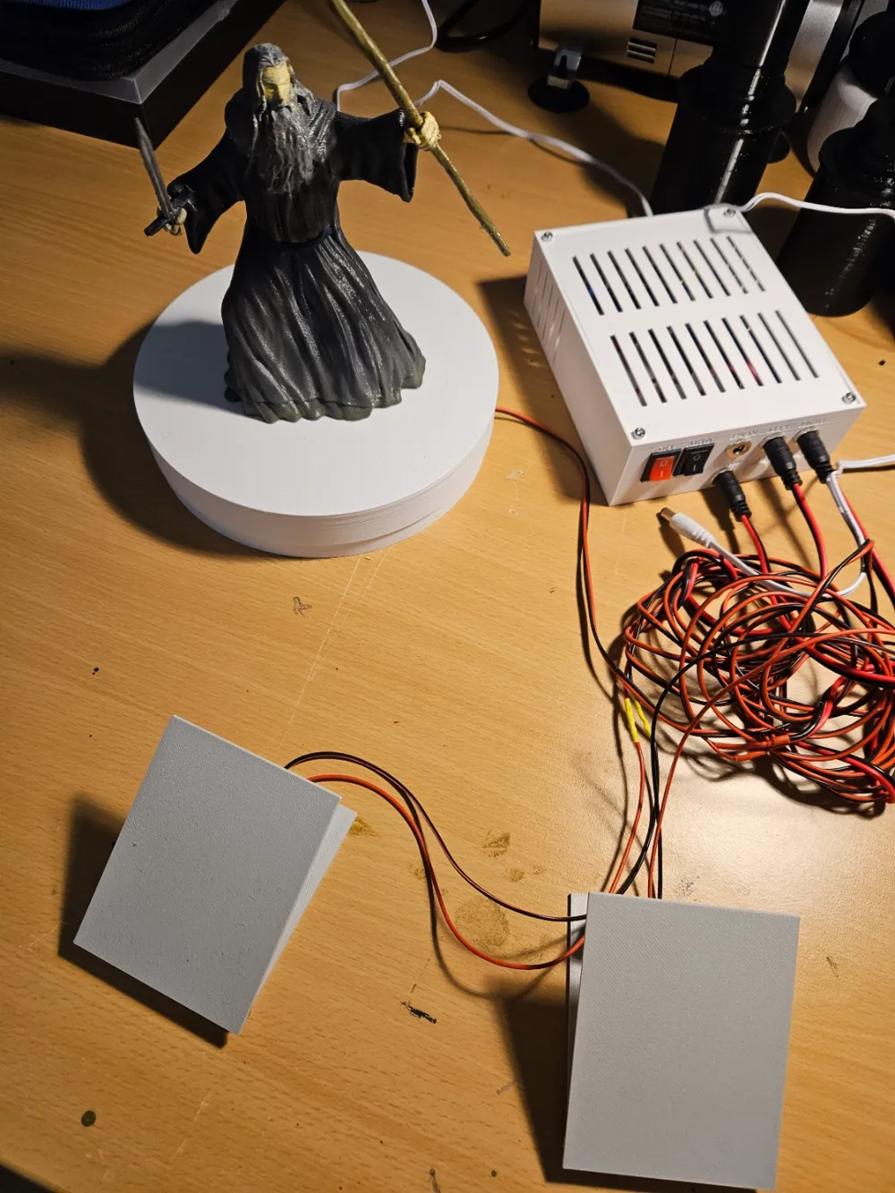
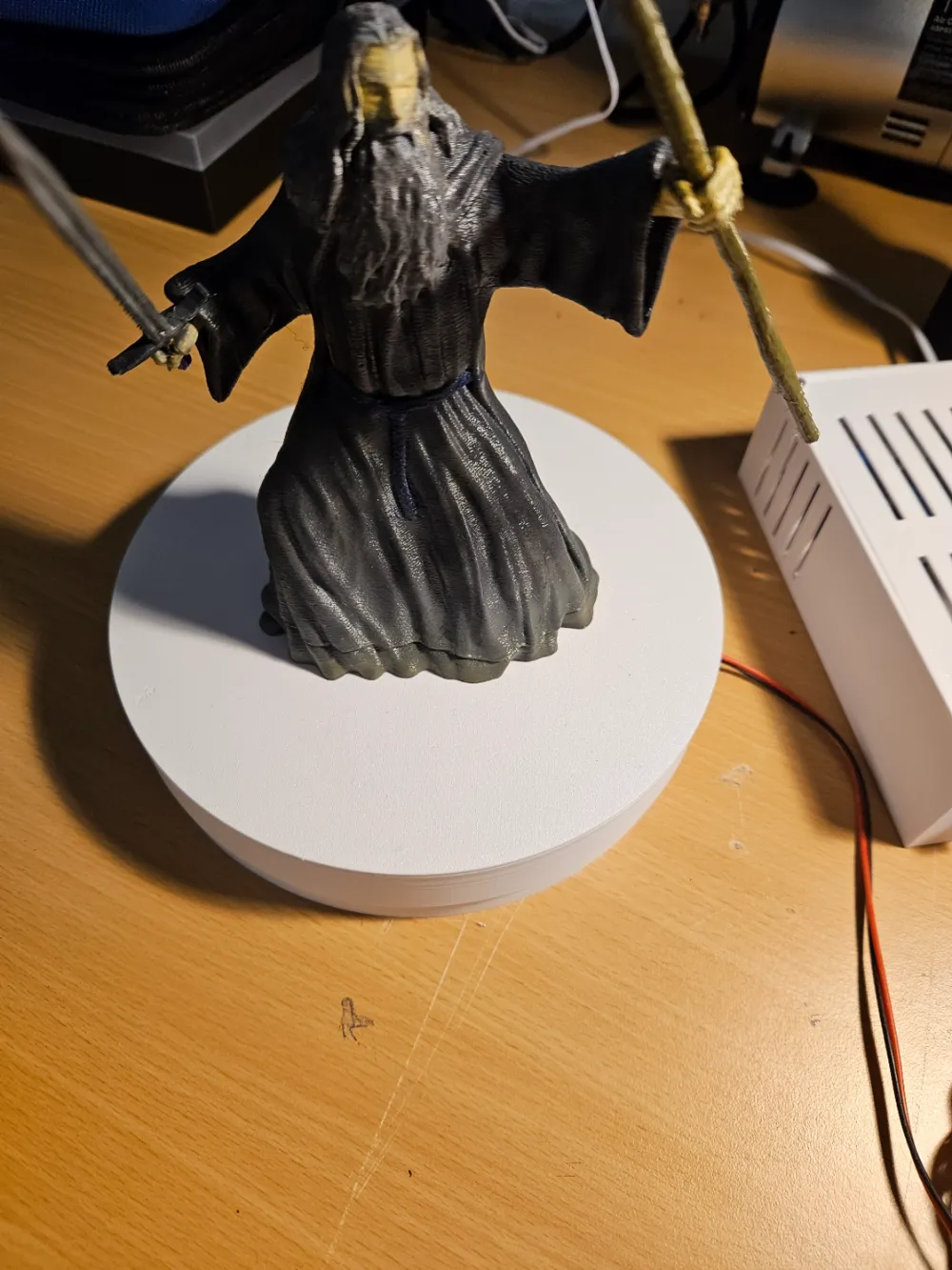
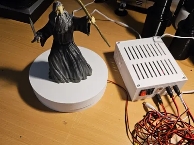
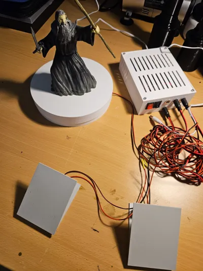
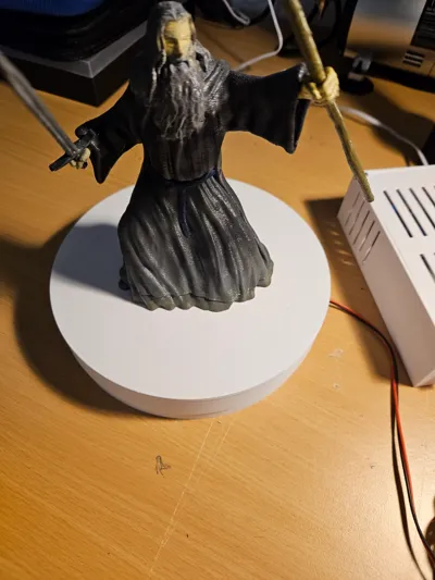
This custom-designed 3D-printed motorized turntable is an innovative and versatile tool for hobbyists, artists, and makers. Controlled via foot pedals, it allows for hands-free operation, letting users adjust both the direction and speed of rotation effortlessly. Additionally, it features an automatic mode for continuous, hands-free rotation at a set speed. Designed with adaptability in mind, this turntable is ideal for a variety of applications, including model displays, painting and airbrushing, sculpting, and photography.
Key Features
Foot Pedal Controls
- Adjust the rotation speed and direction without using your hands.
- Provides smooth and responsive control for precision tasks.
Customizable Rotation Speed
- Variable speed settings allow for both slow, detailed work and faster rotation when needed.
- Ideal for painting, sculpting, or showcasing models.
Bidirectional Rotation
- Switch between clockwise and counterclockwise rotation to suit different tasks.
- Useful for evenly applying paint or working from multiple angles.
Sturdy and Stable Design
- 3D-printed frame ensures durability while remaining lightweight.
- Balanced rotation for smooth and consistent performance.
Multi-Purpose Functionality
- Model Display Stand: Showcase 3D prints, collectibles, or scale models dynamically.
- Painting and Airbrushing Platform: Rotate pieces smoothly for even coatings.
- Photography Turntable: Capture product shots and videos with controlled movement.
BoM
For this build you will need the following items
12v DC Motor 60rpm (You could maybe go up to about 100rpm though): https://www.amazon.de/-/en/gp/product/B07ZKL3VKC/ref=ppx_yo_dt_b_search_asin_title?ie=UTF8&th=1
L298N H Bridge Motor Driver: https://www.amazon.de/AZDelivery-Stepper-Controller-AZ-L298N-Arduino/dp/B0BV79NX3B
Arduino Uno R4: https://www.amazon.de/Arduino-WiFi-ABX00087-Microcontroller-Built-multi-coloured/dp/B0C8V88Z9D
1 x 608zz bearing: https://www.amazon.de/dp/B09PVDDBWF
6 x 5mm ball bearings: https://www.amazon.de/-/en/sourcing-Pieces-Stainless-Bearing-Precision/dp/B09FDL8YHB
Terminal Blocks (2 x 2, 1 x 4): https://www.amazon.de/-/en/Electrical-Positions-Connector-Terminals-Screwdriver/dp/B0CK18PG89/
5 x Barrel and plugs: https://www.amazon.de/dp/B089DXQDS9
2 x Pressure Switches: https://www.amazon.de/dp/B08CY5437N
Male to Female and Male to Male dupont wires
22 AWG Wire approx 6m
2 x Micro Limit Switches: https://www.amazon.de/GOLRISEN-Miniature-Mechanics-Electronic-Automatic/dp/B07F9QKTQQ
12v DC power supply
Ten M3x10mm bolts
Four M3x16mm bolts
Five M3 nuts
1 x M3x4mm lug nut
Printing
As well as the print profile above, you will also need to print two of this model (the parts are included in the above BoM): https://makerworld.com/en/models/1073417#profileId-1063782
Building
Base Unit
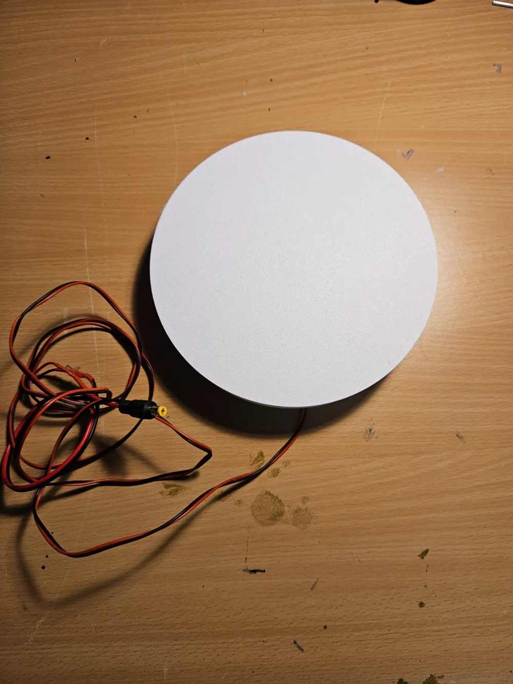
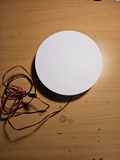
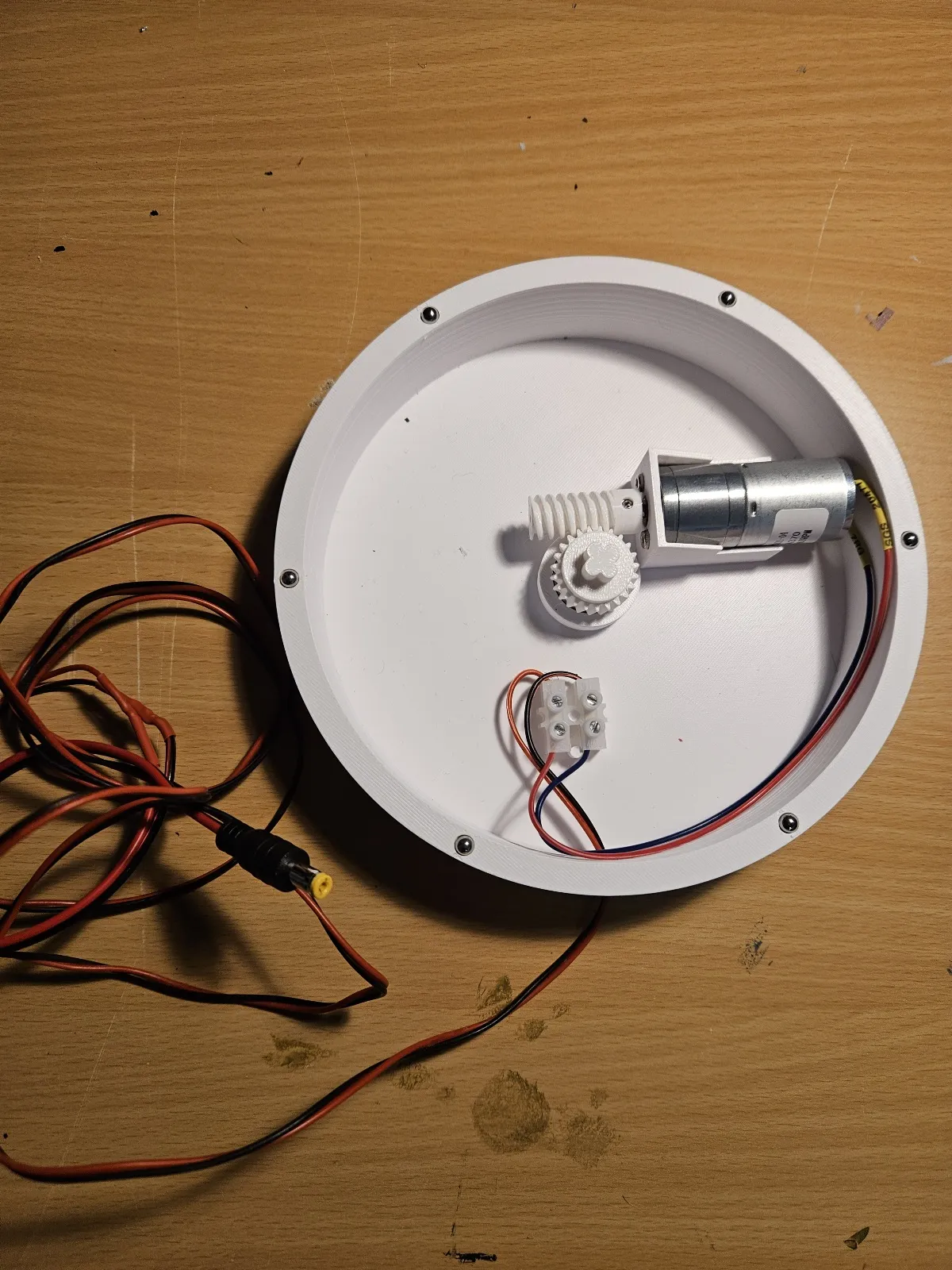
Attach 2 wires to the DC motor (approx 10 to 15cm) and using a terminal block attach them to another length of wire (I used approx 1.5m but your use case may differ). Connect a barrel plug to the end of the wire for connection to the base unit.
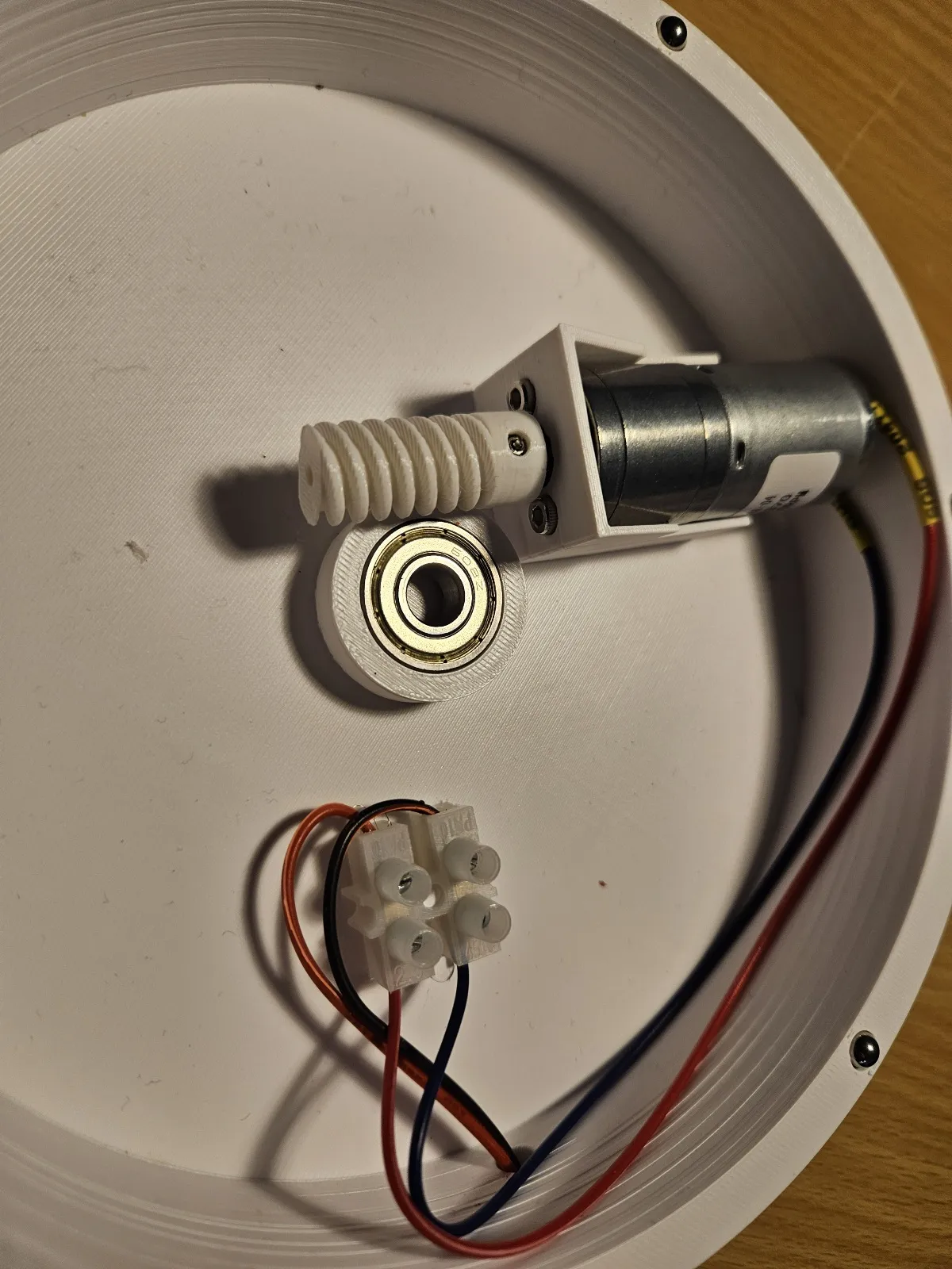
Place the motor in the base unit and secure with 2 x M3x10mm bolts.
Push the 608zz bearing into the center slot, this is friction fit and designed to be a tight fit.
To attach the worm gear insert an M3 nut into the designated hole and use the lug nut to securely attach the worm gear.
Insert the gear into the bearing and add the 5mm bearings to the outer edge of the base unit.
Add the lid to finish the base unit.
Foot Activated Limit Switches
Please see the instructions in this model for building the foot switches: https://makerworld.com/en/models/1073417#profileId-1063782 all materials are included above.
Once assembled add a length of wire and a barrel plug for connection to the base unit. I used approx 1.5m of two core AWG for the wire for each pedal, your use case may differ so ensure they are long enough for your application.
Control Box
The heart and most complicated part of the build, but should still be fairly easy.
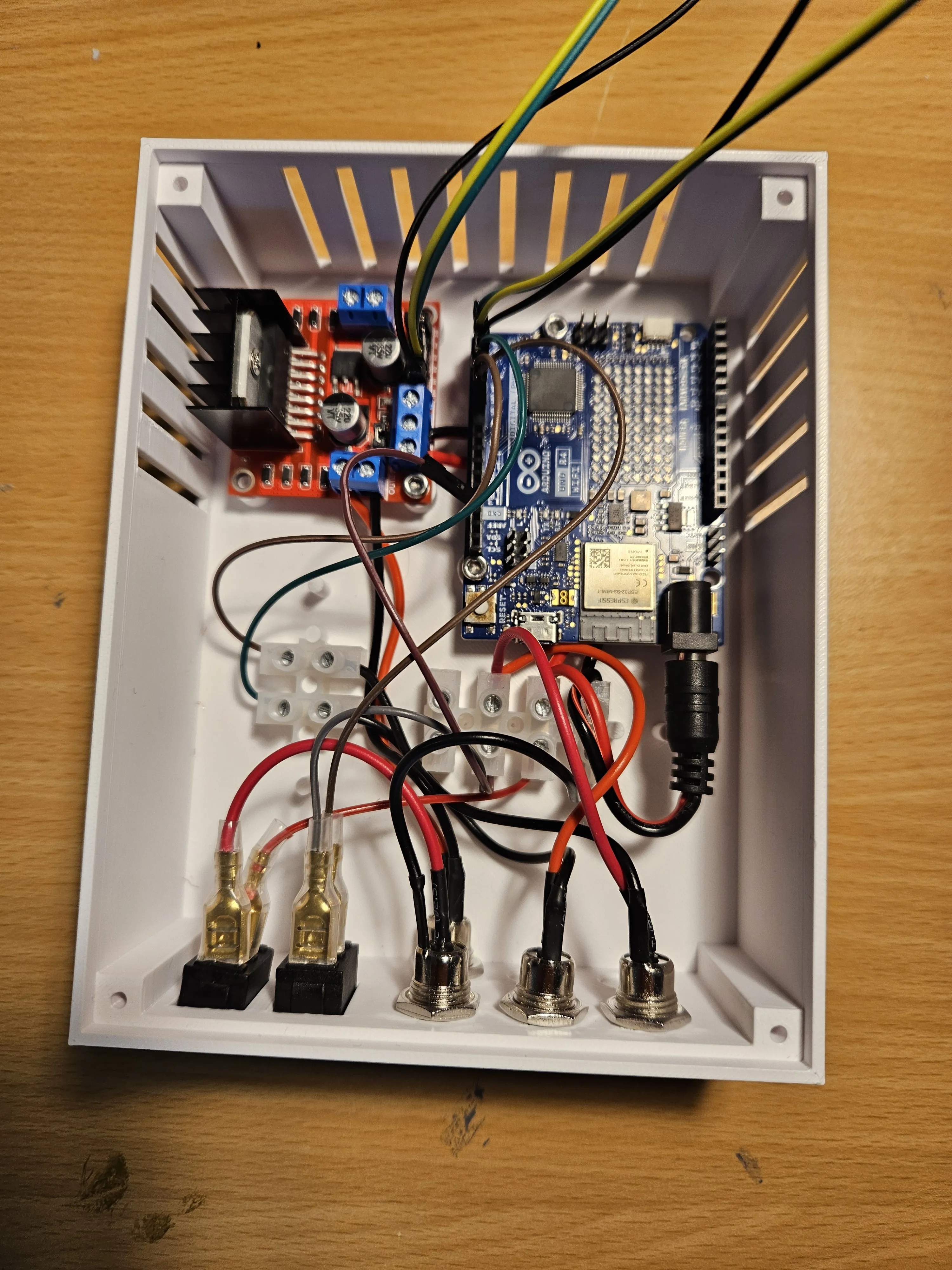
Download the code required to operate the foot controls from github: https://github.com/k3ldar/Arduino/blob/main/rotating_table/rotating_table.ino and upload it to the arduino.
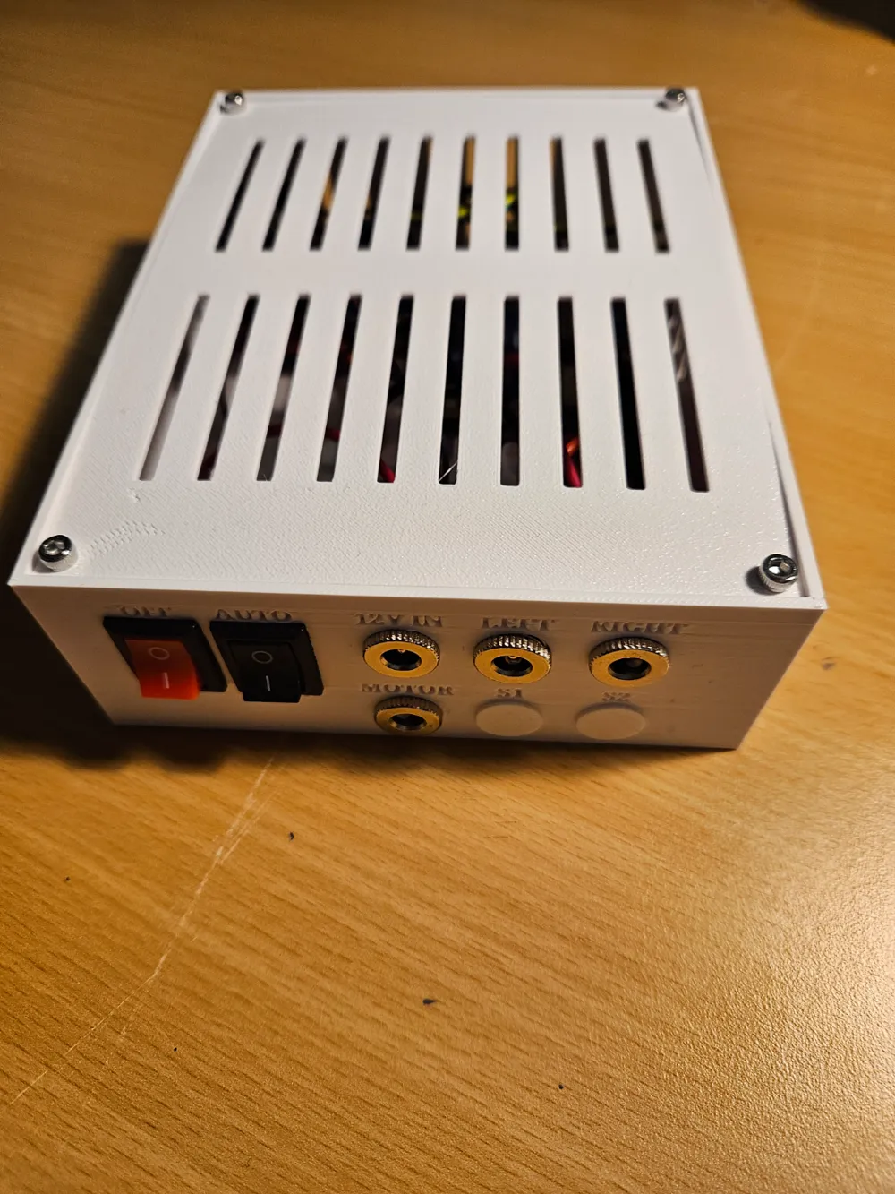
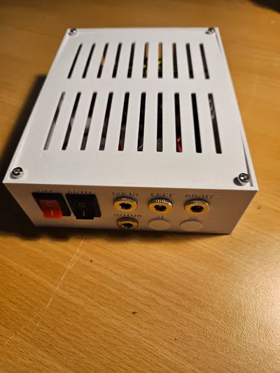
Add the barrel plugs referred as BP1 to BP4
BP1 - 12v In
BP2 - Motor In
BP3 - Left foot pedal
BP4 - Right Foot pedal
Switch1 - Primary on/off switch.
Switch 2 - Auto manual switch.
BP1 negative connects to a terminal block.
BP1 positive connects to switch 1 up position.
Switch 1 lower position connects to terminal block.
From 12 v terminal connections you need to add a DC plug for the Arduino and a direct connection to the L298N (12v in at the front facing Arduino in the image)
BP2 connects to L298N motor 1 slot.
BP3 and BP4 have the red wire connected to a terminal block, the Arduino ground is connected to the other side of this block.
BP3 black wire connects to a terminal block, which is then connected to Arduino D4 using a male Dupont wire.
BP4 black wire connects to a terminal block, which is then connected to Arduino D5 using a male Dupont wire.
Switch 2 upper connects to a terminal block with Arduino ground.
Switch 2 lower connects to a a terminal block, which is then connected to Arduino D6 using a male Dupont wire.
L298N is connected to the Arduino using female to male Dupont wire as follows:
D1 - Motor Left
D2 - Motor Right
D3 - PWM (remove the terminal connector for motor 1 PWM from L298N first)
Help
If in doubt please ask for help, happy to oblige where I can.
Check and Test
When wiring the control box, ensure you test connections where possible to validate everything is working as expected.
Operation
The foot pedal operation operates slightly different depending on whether you are in automatic or manual mode
Automatic Mode
Ensure Switch 2 is in the Auto mode:
- Left pedal decrease speed
- Right pedal increase speed
- Both pedals for 3 seconds resets to default speed (30%)
Manual Mode
Ensure switch 2 is in the MAN(ual) mode:
Left pedal rotate counter clock wise
Right pedal rotate clock wise
Press the opposite pedal briefly to decrease speed
Press the opposite pedal for 1 second to increase speed
Press both pedals for 3 seconds to reset to default speed (30%)
Summary
If you decide to print this model I hope you enjoy, it was a fun build from my perspective and I plan on creating both a photo and spray booth addition in the near future.
License

You shall not share, sub-license, sell, rent, host, transfer, or distribute in any way the digital or 3D printed versions of this object, nor any other derivative work of this object in its digital or physical format (including - but not limited to - remixes of this object, and hosting on other digital platforms). The objects may not be used without permission in any way whatsoever in which you charge money, or collect fees.


Comment & Rating (8)