
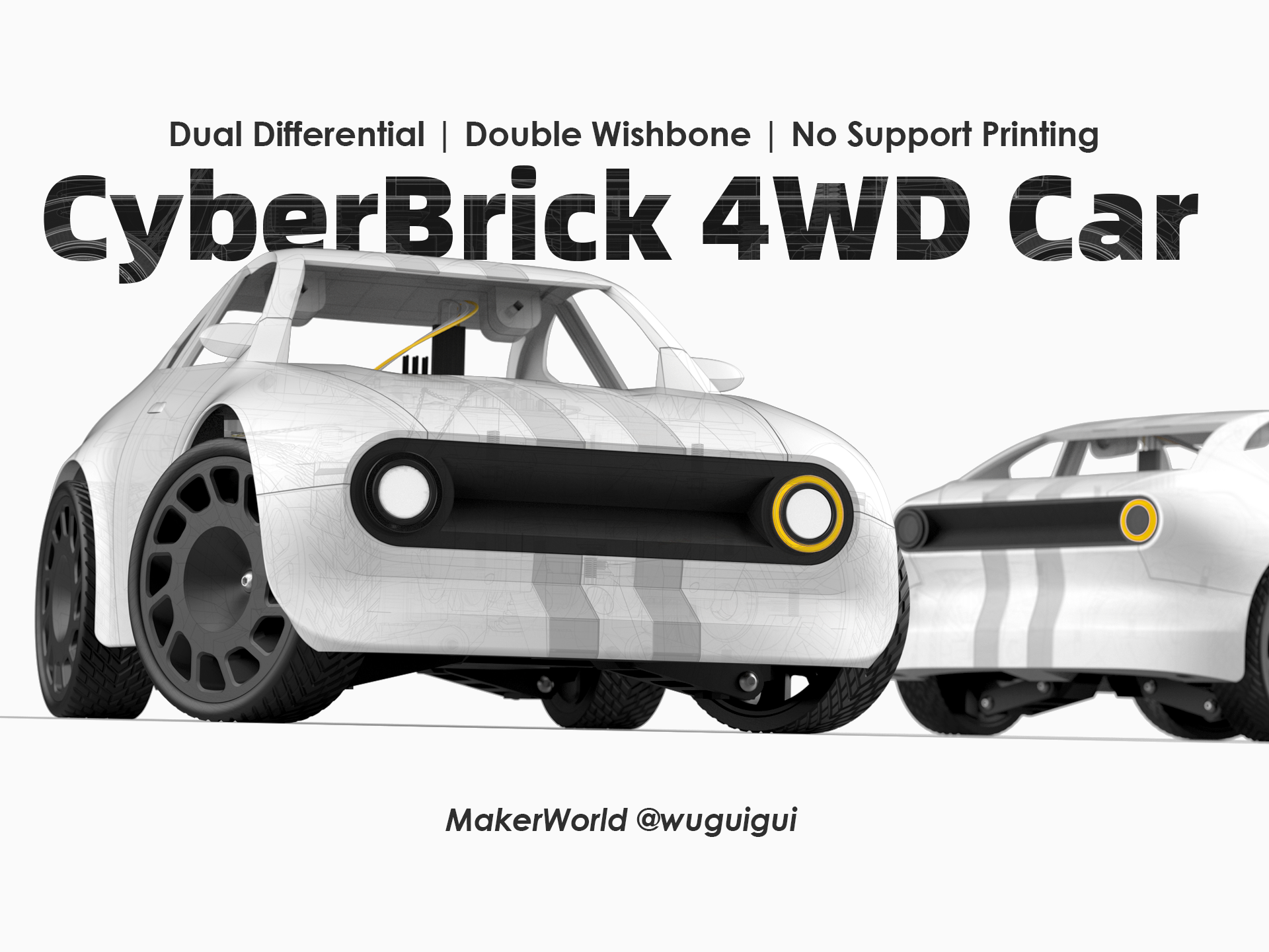
Recently, I uploaded a new CyberBrick model—the CyberBrick 4WD Car. It received a lot of likes, and many people have been curious about how I designed it. So today, I’d like to share the story behind this project and walk you through my design process.
As I mentioned in my previous model, “CyberBrick 4X4 Jeep”: “I have always wanted to design an RC 4×4 vehicle by myself since I was a kid…”. I began studying Industrial Design at Zhejiang University in 1999. After starting my master’s degree in Design in 2003, I also began working as an industrial designer alongside my studies. Throughout all those years of learning and professional practice, I never forgot my childhood dream.
For a period of time, I designed many kids’ ride-on cars. Some of these designs were put into production and sold through ToysRUs. However, I also had many concept designs that remained on paper. One of these concepts was posted on Lofer.com in 2016, as shown in the image below.
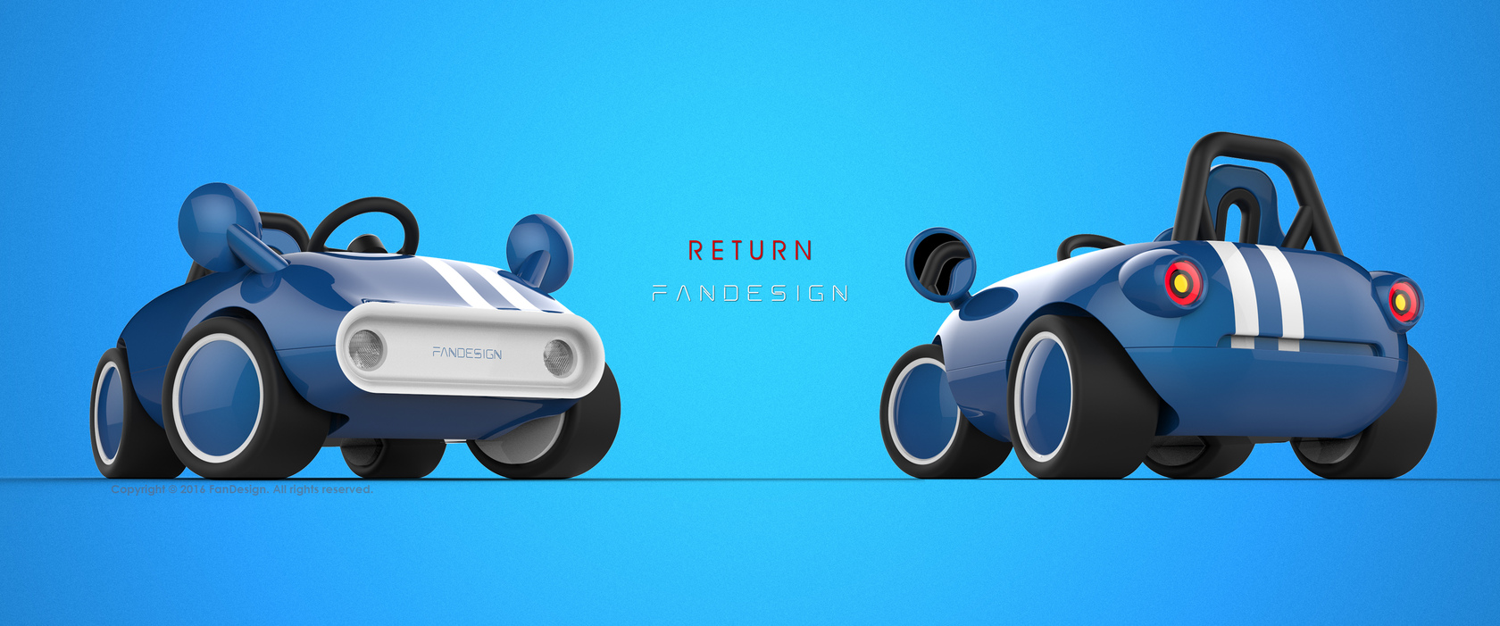
This concept car featured a simple, retro-inspired design. At that time, I never imagined that I would one day bring it to life—especially after I started working as a university lecturer and left the kids’ ride-on car design field.
In 2019, I began using 3D printers to design things in my spare time. I quickly realized that these machines could help designers not only create prototypes, but also produce functional objects for daily use. From then on, I started enthusiastically designing models specifically optimized for 3D printing.
In 2025, Bambu Lab released a revolutionary kit called CyberBrick, which enables makers to create RC models based on 3D printing. This greatly expanded the application possibilities of desktop 3D printing. I really liked the CyberBrick kit, so in 2025 I designed three CyberBrick models: CyberBrick Tank, CyberBrick 4X4 Jeep, and CyberBrick 4WD Car. All of them achieved high download numbers and received many likes.
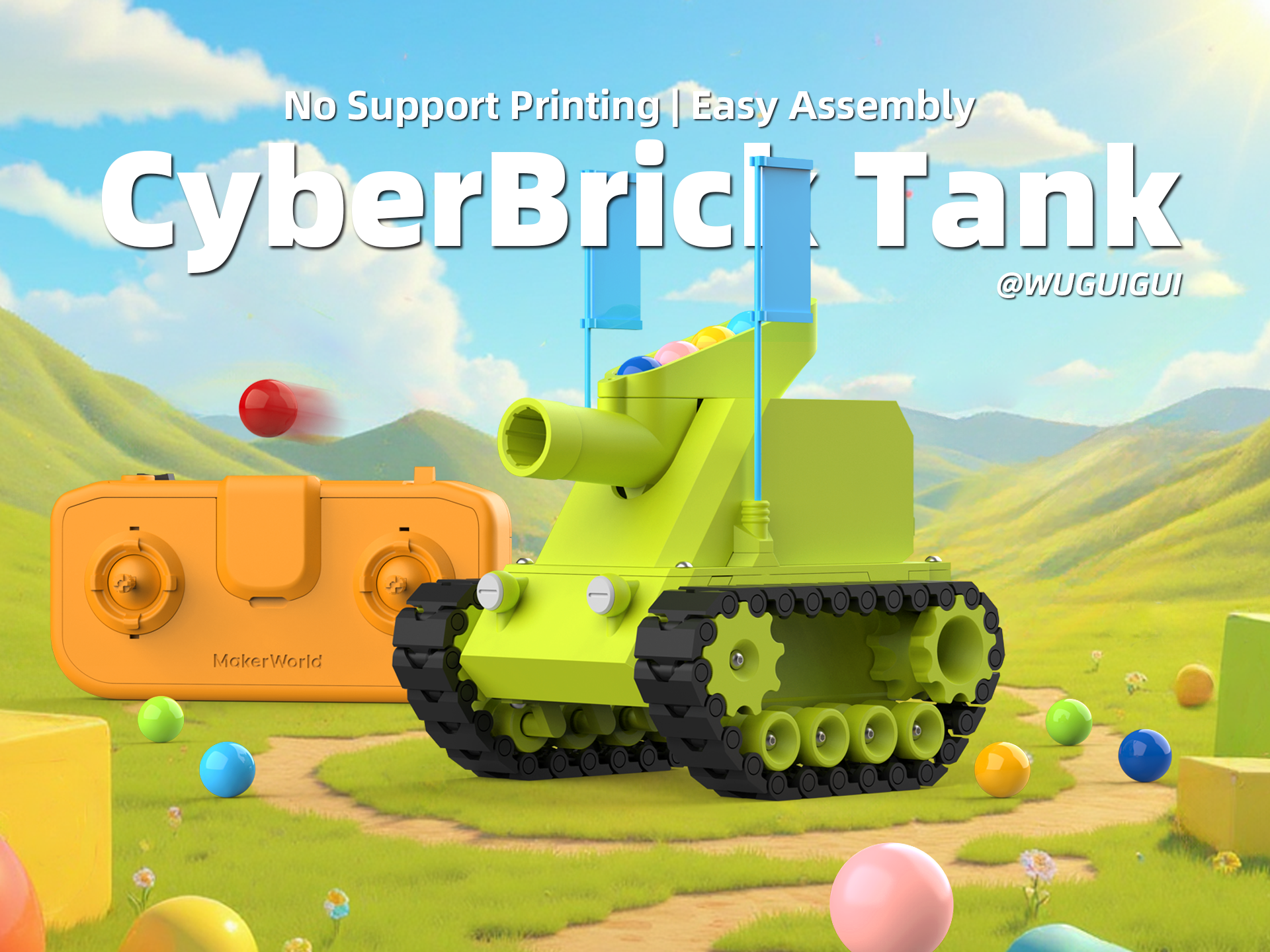
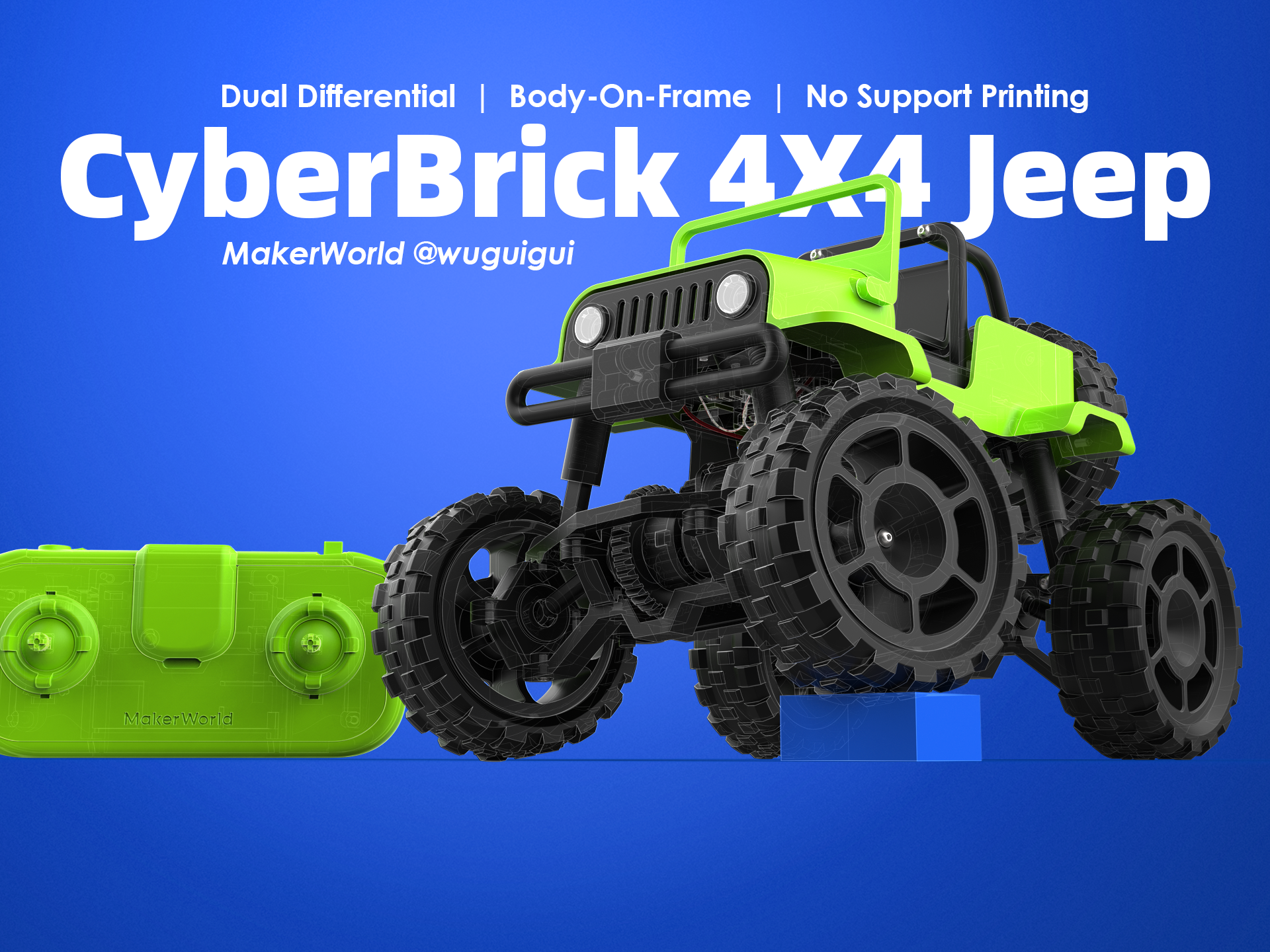
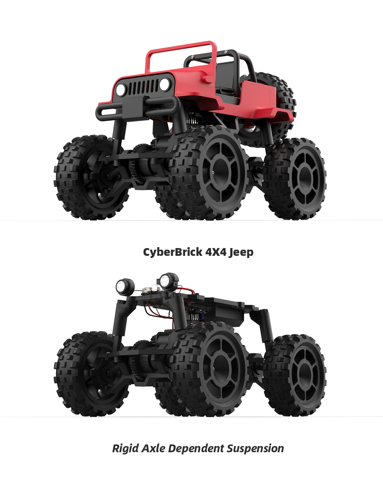
When I started designing the CyberBrick 4X4 Jeep, my main goal was to verify whether 3D-printed parts could realistically achieve a four-wheel-drive transmission structure. Inspired by LEGO Technic parts, I designed a series of new 3D-printable components that could be printed without supports. The result was very successful: a 4×4 Jeep with two differentials and a rigid-axle dependent suspension. After uploading it to MakerWorld, it became very popular. This success encouraged me to design a new car based on it.
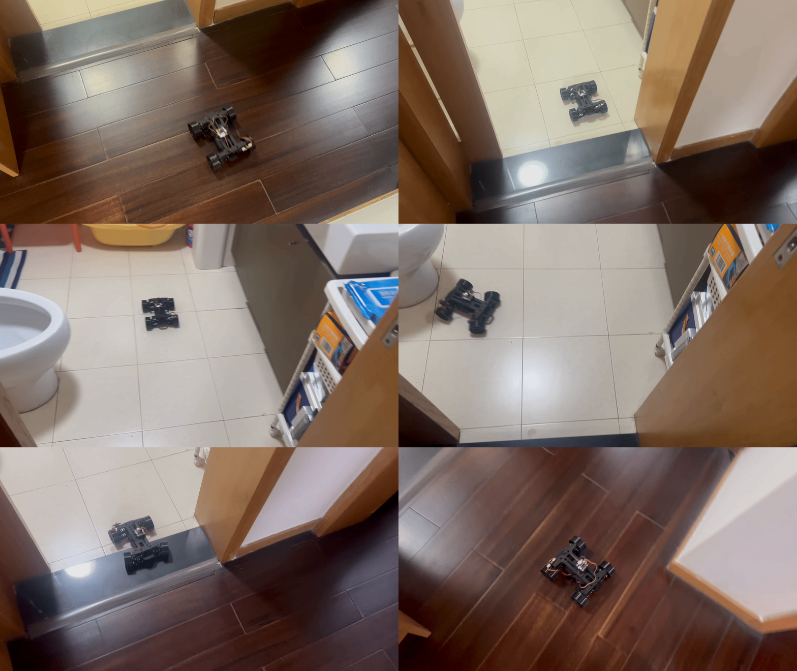
First, I designed a new chassis featuring double-wishbone independent suspension, which is more compact and faster than the CyberBrick 4X4 Jeep. The next challenge was designing a body shell that could properly match this chassis. At that point, I recalled the concept car I had designed years earlier.
Another major challenge was designing a combined lighting system, where the headlight and indicator are arranged as concentric circles.
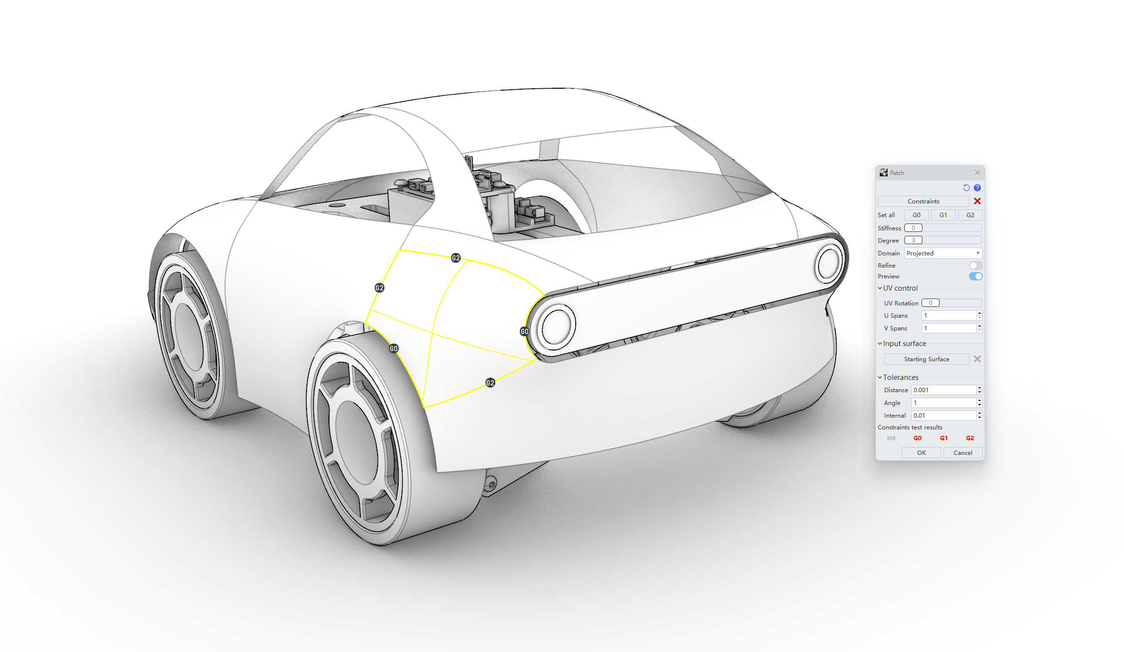
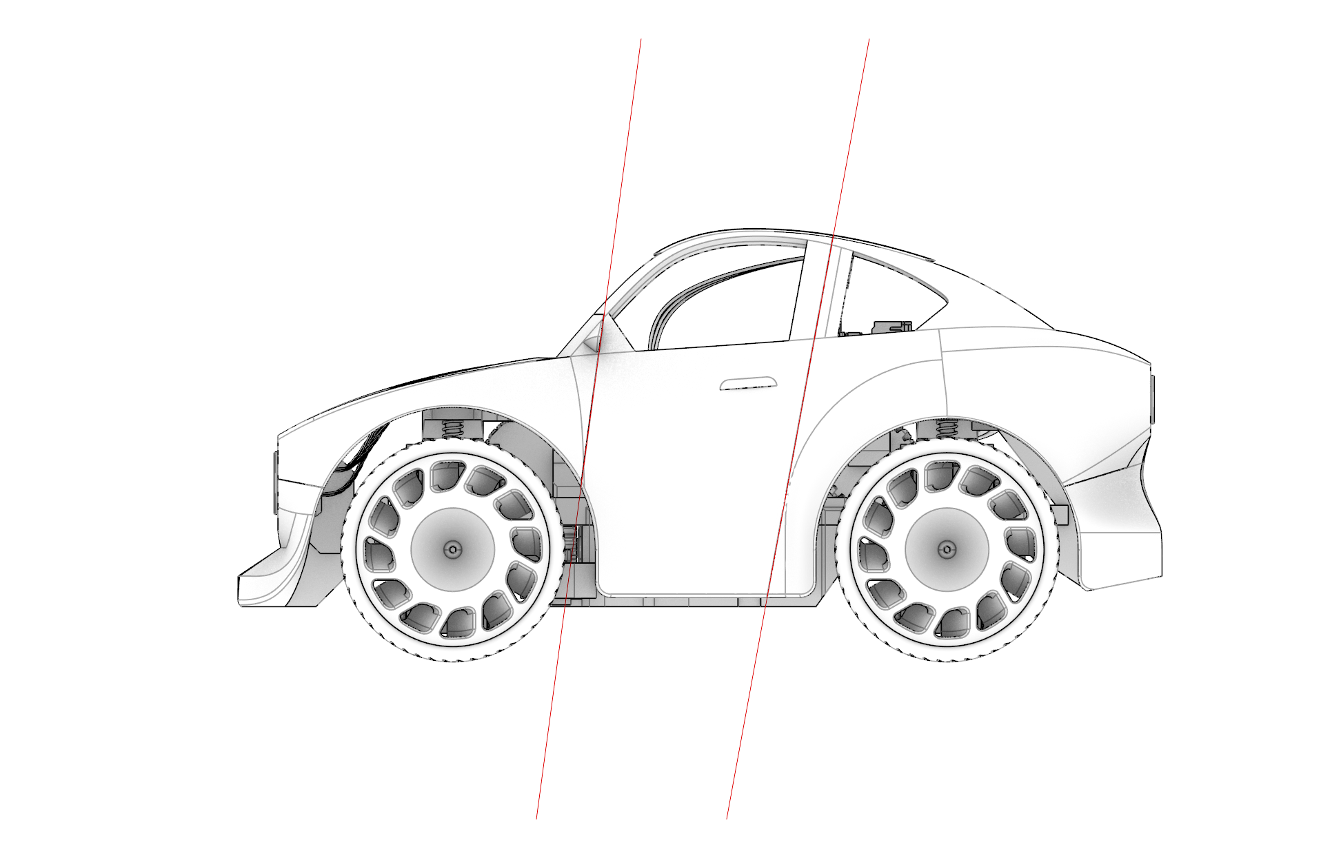
Many people have commented that this car looks like the Honda e or other similar models, but in fact, it comes from my original design—though it is, of course, influenced by many previous car designs. I modeled the car body using Rhinoceros 9 (WIP version), which includes a new Patch tool capable of creating G2-continuous surfaces from more than four edges. This tool was extremely helpful for car body surface modeling. You can see an early version of the body shell in the image below.
The entire body shell went through at least five major versions, and I can’t even count how many detail modifications were made. I don’t usually save too many intermediate versions, as doing so interrupts my creative flow. I believe this is also one of Rhinoceros’ strengths: unlike many engineering-oriented CAD software packages with rigid workflows and procedural logic, Rhino feels much more like a designer’s tool.
From the images below, you can see how the body shell evolved, including the initial design of the front bumper. I struggled with the bumper style for a long time before deciding to use an integrated bumper rather than a separate one.
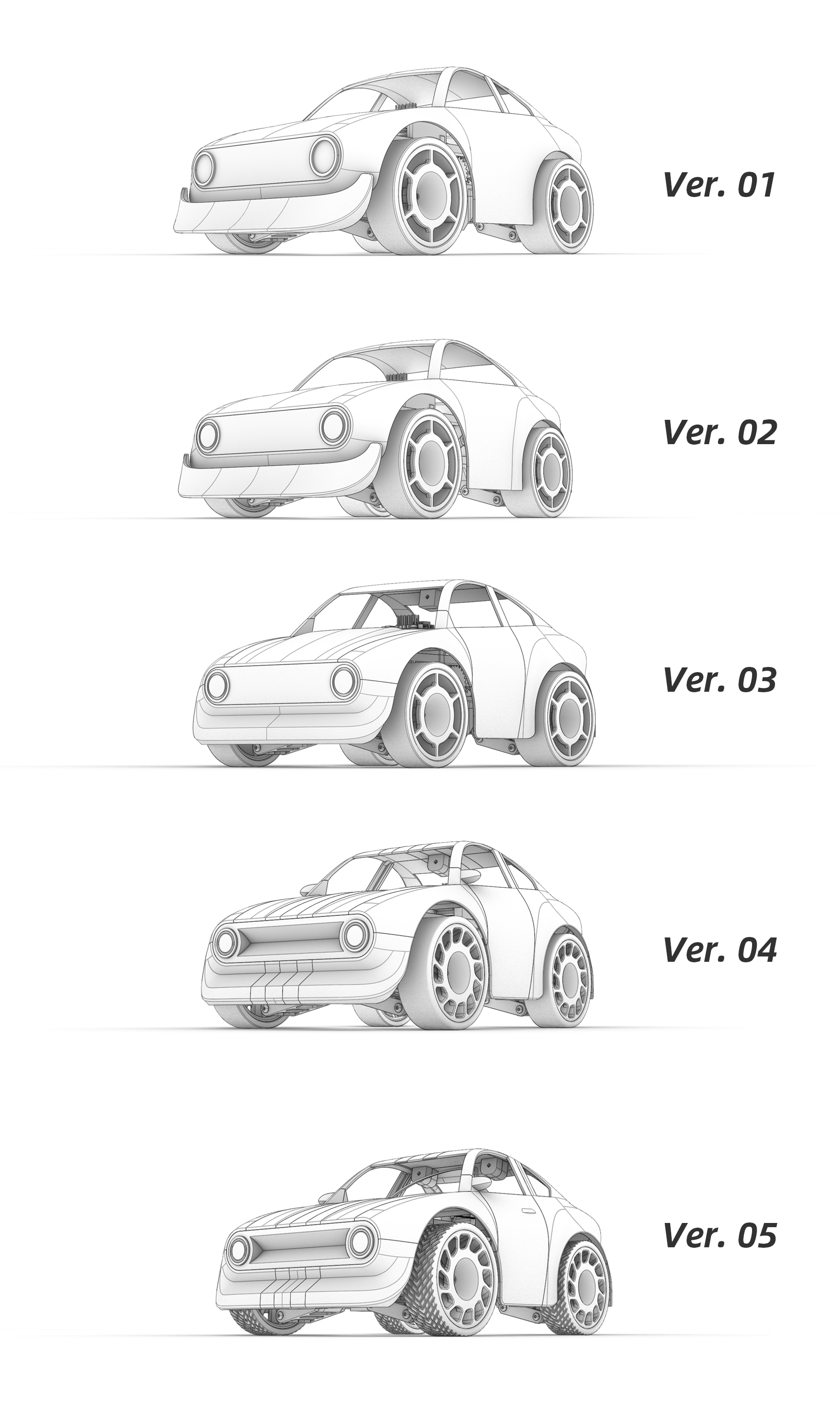
From Ver.03, I began seriously considering the “No-Support Printing” strategy for the car body shell parts, as well as the most challenging component—the “Combined Lighting System”.
“No Support Printing”
Many of my models carry the label “No Support Printing”, meaning that all parts can be printed without supports. All three of my CyberBrick models follow this principle. Achieving this in the CyberBrick 4WD Car was particularly challenging.
To make it possible, I had to:
- Split the body shell into several parts
- Cut the shell from the sides with two delicate slashes
- Make the bottoms of the front and rear bumpers flat
- Add specific angled surfaces to certain details
All of these efforts allowed every body shell part to be printed without supports.
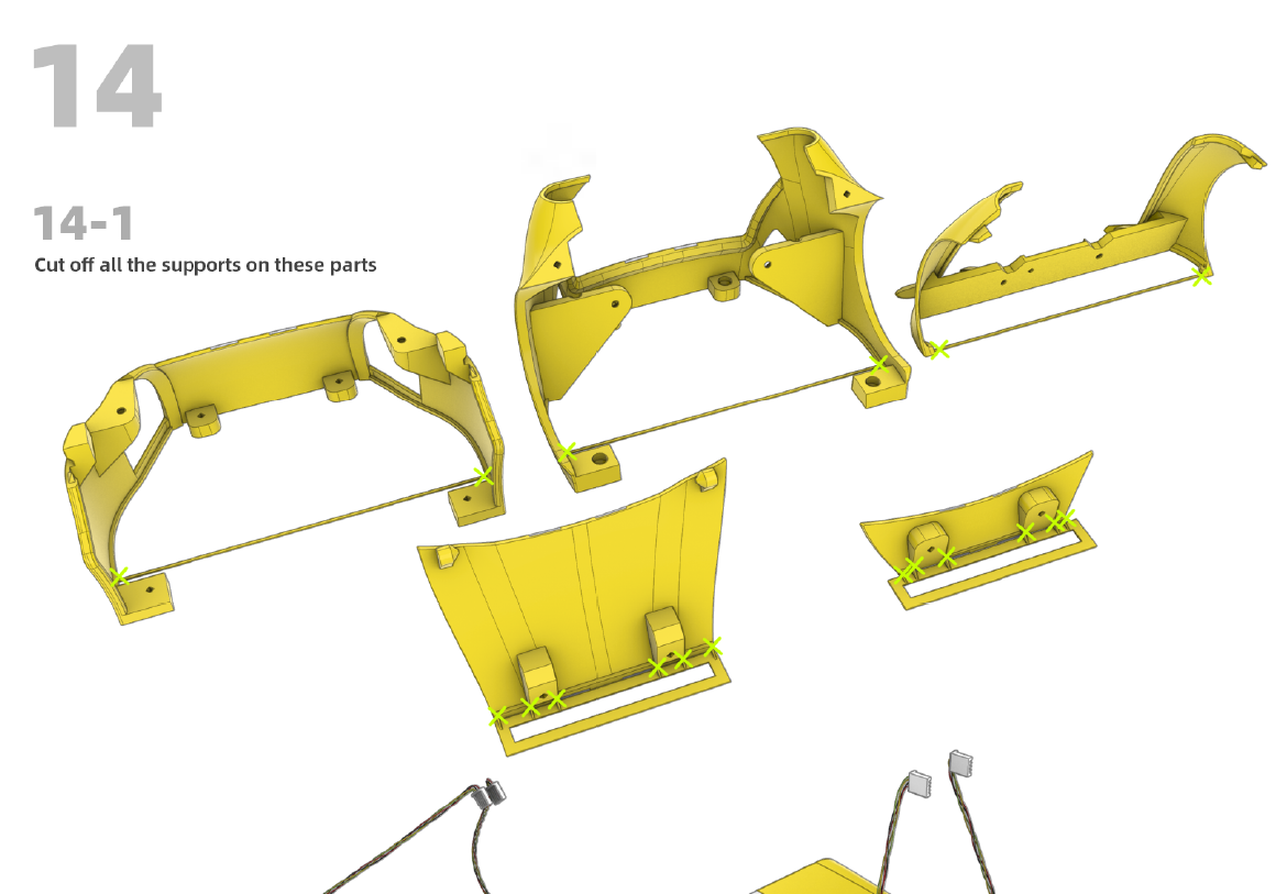
The most critical technique here is what I call “manually generated support.” After separating the body shell, I found that the bottoms of many parts were too narrow and could easily fail during printing without additional assistance. To solve this, I added additional support structures, which can be seen in the assembly guide.
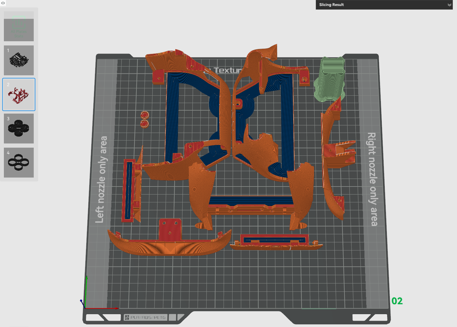
These additional supports can help to generate inner brims with a 0 mm gap in Bambu Studio, as shown in the image below. They are easy to remove after printing and do not affect surface quality. Since all brim edges are located on the back side of the body shell—similar to undergated parts in plastic model kits—the visible surfaces remain clean. I first applied this technique in the CyberBrick 4X4 Jeep. In the CyberBrick 4WD Car, I expanded its usage and, for the first time, added additional lines to shape the inner brim areas in certain parts.
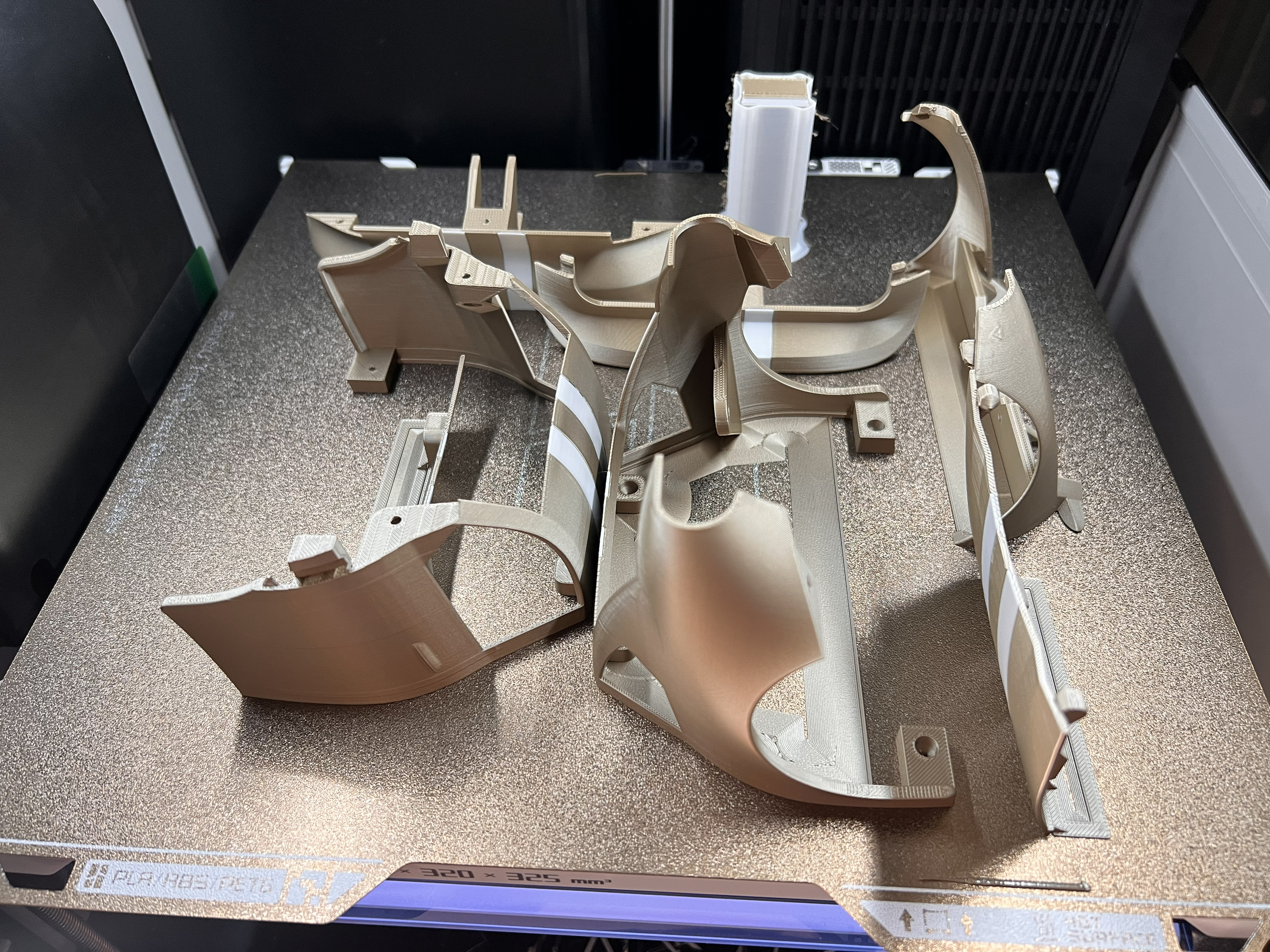
BTW, numerous detail refinements were made to the body shell not only to achieve “No Support Printing”, but also to enhance its structural strength.
Combined Lighting System
From the moment I first used the CyberBrick kit, I wanted to design a more advanced lighting system. In my earlier models—the CyberBrick Tank and CyberBrick 4X4 Jeep—I followed the official LED setup guide. However, I soon discovered a limitation: in the CyberBrick app, when you combine the indicator and headlight into a single LED, turning the indicator on and off also turns the headlight off. As a result, many creators set the headlight to turn on when the indicator is off, which means the two cannot be controlled independently.
I wanted to solve this by placing the headlight and indicator on 2 separate LEDs connected to 2 different LED hubs. At the beginning, I didn’t realize that the limited length of the LED wires would become a major issue later.
The first challenge was designing a concentric lighting assembly: the headlight in the center and the indicator as an outer ring. This required ensuring that both LEDs could function independently, without interference, while keeping the overall assembly as compact as possible.
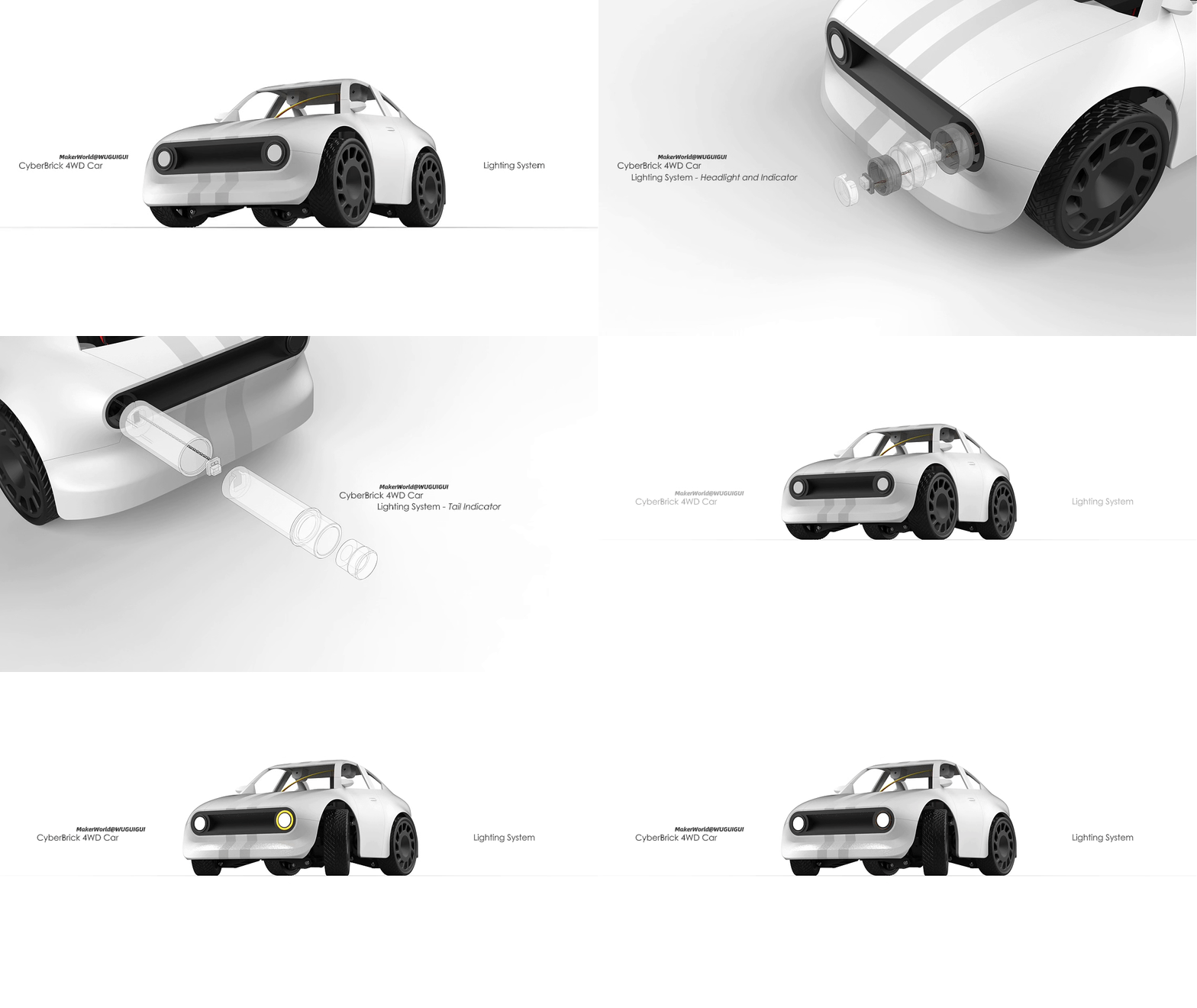
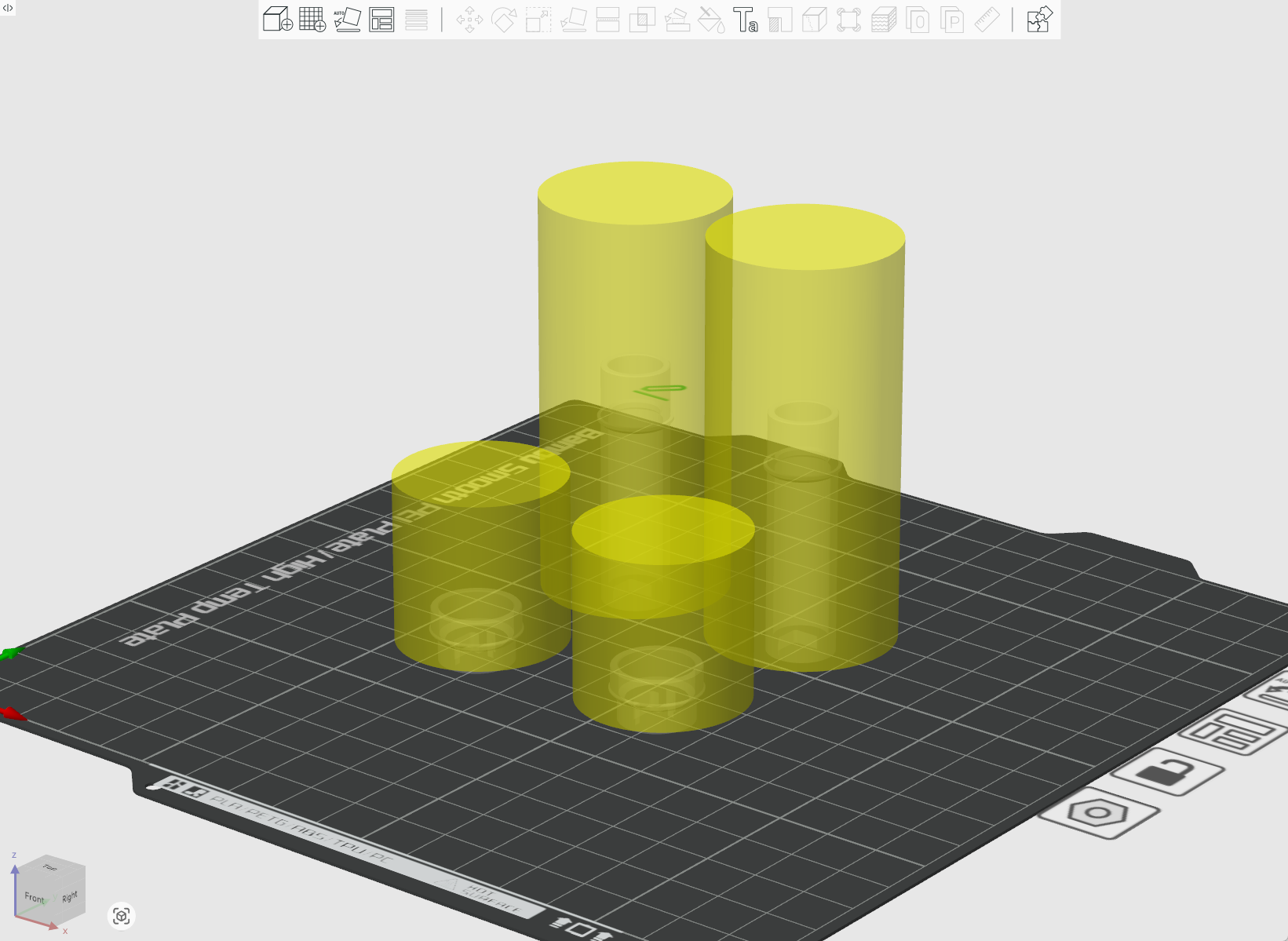
I went through many iterations to achieve this. I printed transparent PETG parts using the most transparency-optimized settings recommended in the Bambu Wiki. To achieve both no-support printing and maximum transparency, I even used “Add Modifier” to apply different print settings to different regions of the same transparent part. You can see this in the print profile named “LED Transparent Parts.”
When I finally achieved full functionality for the first time, I was extremely happy—but that excitement didn’t last long.
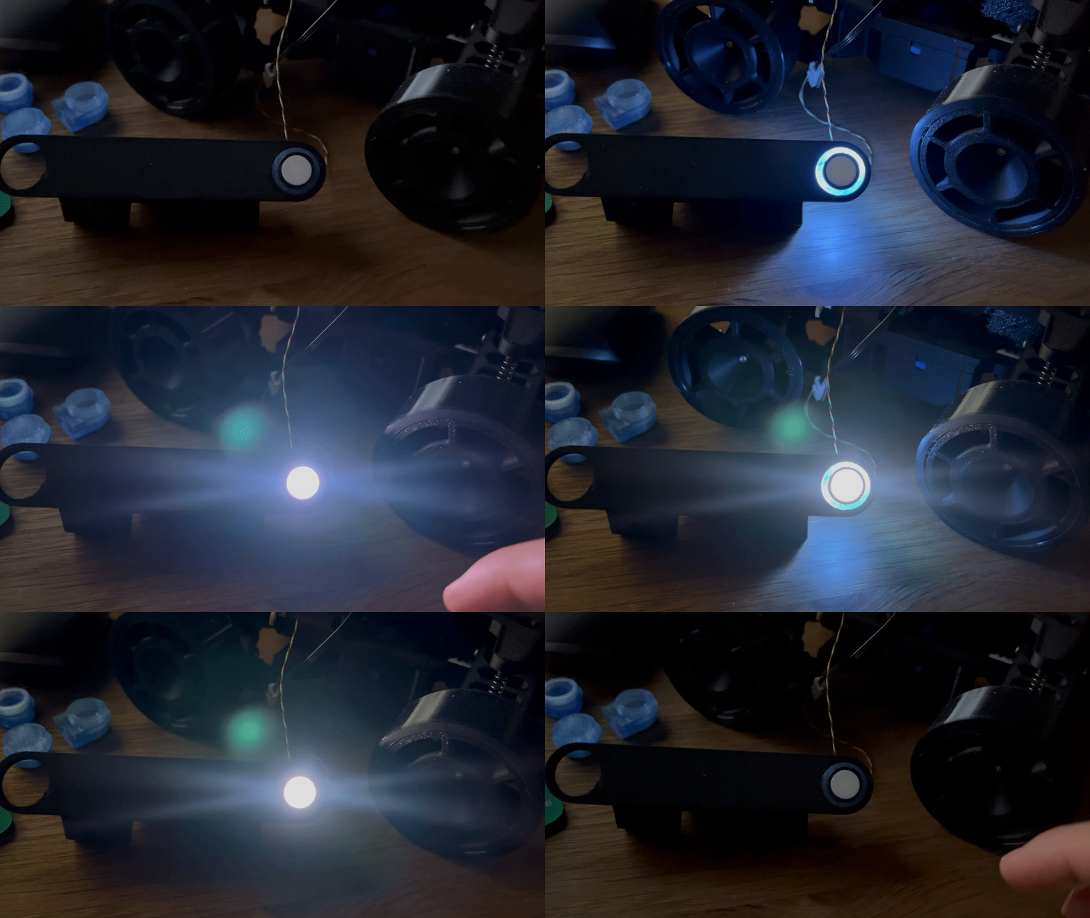
I soon realized that the LED wire length is only 10 cm, which is not long enough to support both front and rear lighting assemblies. Since all indicator LEDs must be connected to one hub—and likewise for headlights and taillights—it’s not possible to place one LED hub in the front and another in the rear. I tried many approaches, but none of them worked.
In the end, I had to make a compromise. I chose to prioritize full functionality of the headlights and indicators, and abandoned the taillight function. Both LED hubs were placed in the front, and I extended the length of the rear indicator’s transparent parts so that the LED wire could still reach the hub. At least in this way, the rear indicators remain functional.
This project explores how design constraints can become creative drivers rather than limitations, while validating a complete workflow from concept to an RC vehicle. It reflects my ongoing exploration of integrating industrial design thinking with 3D printing technologies. In short, with the support of 3D printing and CyberBrick, I was able to realize my childhood dream. Thank you, Bambu Lab! Thank you, MakerWorld! Thank you, CyberBrick! I will continue exploring along this path.


