i6 functional design


Print Profile(1)

Bill of Materials

Description
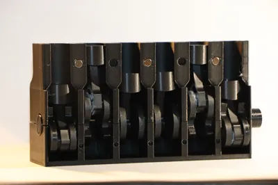
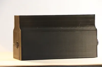
This is an inline 6 engine that I created for the engines contest. I started designing this model based on the famous RB26. During the design process, I deviated from the RB26 and focused more on actually making it reliably work.
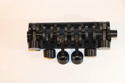
To put the piston head on the piston rod, you must use the piston connector, which you can push in. It might be a little tight at the beginning but it should fit very snug. Make sure that it does not stick out, otherwise the motion of the pistons will not be smooth.
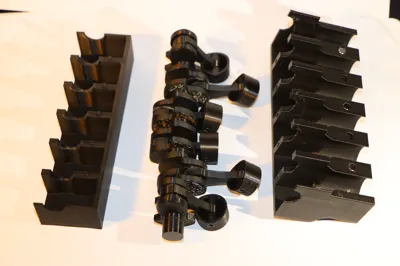
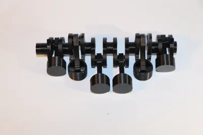
There is one step that requires some type of glue, and that's the assembly of the crankshaft. These are link1 through link7 all in the order that I named them. The hole will probably be filled up with support material that you will have to remove with an exacto knife so be careful to not cut yourself!
When gluing them together, make sure that the piston rod is in place on the shaft that you're gluing. To line them up correctly, make sure that the shapes that are glued together match so that they look symmetrical. The first and the last are in the same orientation, the second and the fifth are in the same orientation and finally, the two middle ones are in the same orientation. I also highly advise doing one at a time and letting them properly dry before putting on another one, since I have had to start over many times because I was impatient with the gluing process. Also, don't use too much glue or you have a chance of gluing the piston rod to the crankshaft.
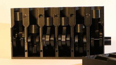
The bottom and the side just click on very easily so that should not be a problem. To put the crankshaft into the housing, I found it the easiest to rotate the crankshaft while lining the piston heads into the holes.
If there are any problems with assembly I can try to create an assembly guide for those who want this.
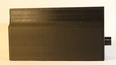
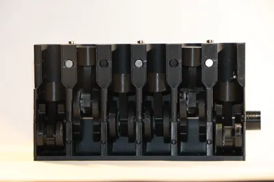
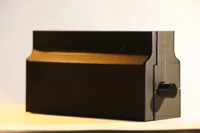
This model works best with a few magnets to snap in place the side cover. This cover can be removed easily. I used 6 5X2mm magnets, there is place for more but you might get away with only using 4.
I ordered everything for printing in a way that is logical for me to keep an overview of what is printed and what needs to be printed. I had difficulties printing and I'm not sure what the cause was so if you experience issues please let me know so I can keep track of what problems I had and what problems you guys have.
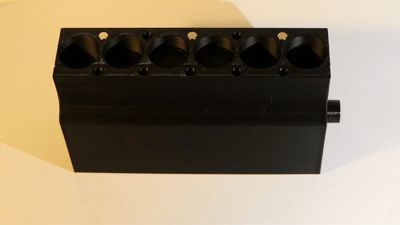
The holes on the top are for an attachment that I am currently still developing which might take a little bit more time and should just click on with magnets.
Edit: I added a new file with a fully assembled crankshaft and piston rods. This replaces the previous solution for those who don't like gluing things together. Printing the crankshaft in one piece isn't easy and I haven't really found a good setting for it yet. I printed it standing up and despite the cleanup necessary it leaves less marks then printing it lying down.
License
You shall not share, sub-license, sell, rent, host, transfer, or distribute in any way the digital or 3D printed versions of this object, nor any other derivative work of this object in its digital or physical format (including - but not limited to - remixes of this object, and hosting on other digital platforms). The objects may not be used without permission in any way whatsoever in which you charge money, or collect fees.
Comment & Rating (3)