Layer Separation Tester


Print Profile(0)
Description
I've been experimenting with interface patterns and how to force two 3D-printed layers to NOT stick, especially for print-in-place, functional parts, and easy support removal. This tool is designed to rigorously test combinations of surface micro-features, patterning, and z-clearance, making it easy to compare and tune the “grippiness” or separability of overlapping layers. Depending on the top/bottom patterns and precise Z-gap, the ease of breaking parts free (or how much they stick) can be dialed in for your application.
As a disclimer all my personal tests have been made in PLA only. Keep that in mind when i recommend variables in this description as your mileage may varry.
Overview
This series of models is a systematic study of how modeling micro-features (0.2 mm default, adjustable) on the top and bottom surfaces of overlapping layers impacts their separation characteristics. The goal is to identify the best pattern combinations and Z-gap values for easy separation while maintaining mechanical function. Results can help dial in both custom supports and reliable print-in-place assemblies.
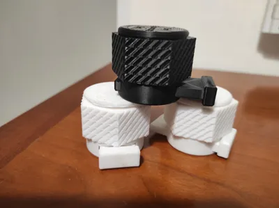
example of these patterns :
Test Methods
There are 3 included test geometries:
Pull Test (Support Removal on 90° Overhangs):
Supports are marked with an “X” for easy grip.
Use pliers to pull and check how cleanly the support comes away.
Shear Test (Push Pin):
Push the test pin out from its seat and observe if, or how, it snaps free.
Twist Test (Large Hex Bolt):
Twist the hex bolt to test rotational breakaway and check for sticking at the interface.
All three specimens are built using identical modifier patterns and Z-gap increments.
Video demonstration :
How to Use (Slicer setup in Orca)
Text version below the video :
STL groups are provided at 0.05 mm Z-gap increments (from 0 to 0.5 mm).
For each test, grab the full set of three files per Z-gap:
The “main” model
“botLayer” modifier
“topLayer” modifier
Make sure all three have the same Z-gap value.
ie : here i choose the 0.4 mm Zgap
Load all three at once in your slicer.

Click Yes When you're prompted if these are parts of a single object with multiple parts
In the Object Tab, rightclick on the TopLayer and BotLayer and change their Type :

Set “TopLayer” and “BotLayer” as modifiers.

In modifier settings, set 0 top/bottom “shell” layers and use just infill (one wall) for the interfaces.
Experiment with infill patterns, line counts, scaling, and flow settings for the interface zone.
Remember this test is made for 0.2 mm layer height
IMPORTANT FOR TOP LAYER SETTINGS
Change your speed settings so that the top layer is extra slow. If you are using the sparse infill settings make sure to change the speed in the "topLayer" modifier :

Basic TopLayerSettings i recommend tweaking for a start (in orange):
Also Change the SparseInfill Density to something in the 40-80% range 
Basic BotLayerSettings I recommend for a start (in orange) :
Note:
This Model uses deliberate overhangs, your slicer will probably try to warn you about this,
do not activate supports or rotate and simply ignore these warnings in the name of science!
ignore this and clik ok when you export your gcode.
“Bottom layers” sit just beneath overhangs (overhang prints on top of these).
“Top layers” form the overhanging pattern.
| “Top Layer ” |
| Z gap in mm |
| “Bottom Layer” |
Refrain from testing with the 2D latice for the TopLayer as it tends to fail the print.
In my experience, linear patterns on top tend to hold best, but please experiment and report results.
Here's what happens of you use a spiral or concentric on the top layer :
Adjust flow and speed for top layer modifiers to further tune separation.
Support marks (“X” text) are included for clarity. There’s also interface pattern labeling and samples on the upper surfaces.
From my initial tests, Z-gap values from 0.3 mm to 0.4 mm seem close to ideal, but your mileage may vary.
If you have any ideas or questions send them in the comments, I check every one.
Customization
If a 0.2mm layer height is not enough feel free to ask me for a different version or tweak the parameters on my fusion360 file.
The parametric Fusion360 (.f3d) file is included, as well a the file for the MINI version.
If you customize the z-depth in the F3D, update the surface text sketch for clarity.
Use “botLayer” and “topLayer” bodies to perform Boolean subtractions if you want to cut custom shapes or patterns into the model directly.
Default micro-feature thickness is 0.2 mm (can be changed via the GcodeLayerHeight parameter in Fusion360).
List of available parameters : 
Video demo of the Fusion360 parameters :
Comment & Rating (0)