Baseball_Pitcher_Project.V01


Print Profile(0)
Bill of Materials


Description
Description
Project developed using Onshape
Edit: the Arduino pet accessory contest (on Printables) concluded 20 minutes after this post’s publication… a month’s work, wasted… due to my Canadian residence, I mistakenly assumed the deadline was 00:00 local time, not European time…
Please 3D print components in PET-G CF for enhanced structural integrity; the black belt should be printed in TPU (70A-90A)
French:
To ensure timely project completion, comprehensive testing was not feasible; only the gearbox underwent testing. Should you encounter issues or complete the project ahead of me, please notify me. I will diligently strive to refine this project, updating each iteration accordingly.
Overview:
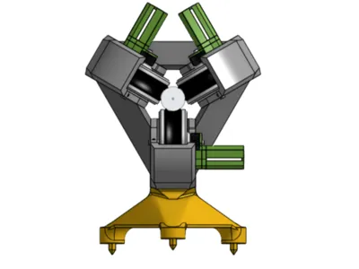
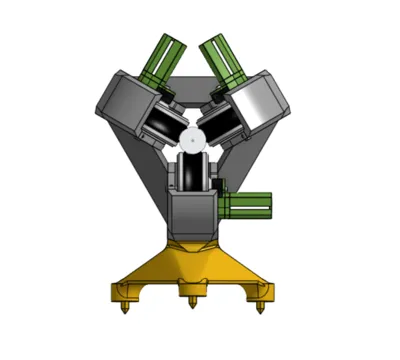
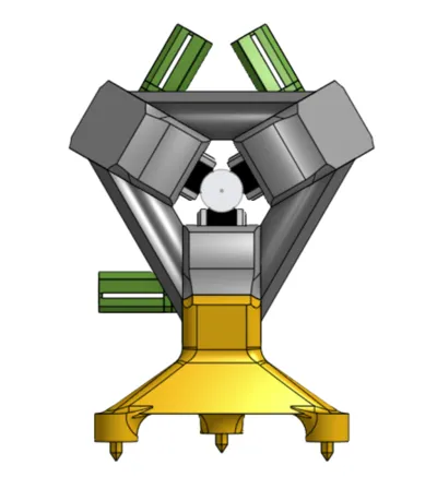
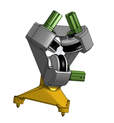
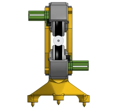
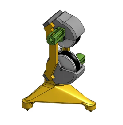
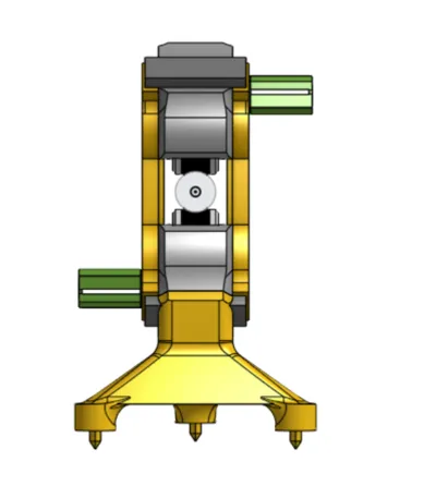
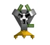
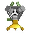
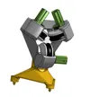
This project presents a motorized baseball pitching machine employing three wheels to propel baseballs at high velocity with variable spin. It is meticulously engineered to synthesize performance, dependability, and operational safety.
Project Genesis:
This pitching machine was conceived for my brother, a participant in a collegiate baseball program. Its purpose is to facilitate efficient training, precluding arm injury for my father who would otherwise manually pitch hundreds of baseballs. This system enables my brother to receive high-velocity pitches repeatedly and safely, obviating reliance on manual assistance.
Project Achievements:
Projectile Velocity: The launcher achieves ball velocities of up to 85–90 mph, accurately simulating game-realistic pitches.
Spin Variation: The three independent wheels allow for nuanced ball rotation adjustments, creating diverse spins (fastball, curveball, slider, etc.).
Adaptability: Compatibility extends to any 75 mm diameter ball, broadening its applications, including outdoor canine play.
Distinctive Project Attributes:
A three-motor, three-wheel propulsion system ensures superior speed and spin regulation. (A two-wheel option exists, offering reduced spin variability)
Custom gearing enhances torque and preserves consistent launch velocity.
Simple adjustments accommodate diverse training regimens and gameplay styles.
A robust design and optimized 3D printing process prioritize durability and performance.
Utilizes CIM motors (one per wheel) and a 12V battery, mirroring FRC competition standards.
FOR PROJECT IMPLEMENTATION, PRIORITIZE SAFETY!!! (I bear no responsibility for injuries sustained during operation; these wheels rotate at exceptionally high speeds, with motors capable of reaching 5500 RPM)
Therefore, employ 14 AWG or 16 AWG cabling for direct battery-to-motor connections, and incorporate a 20–30A fuse between the battery and the assembly for enhanced safety. MOSFETs
| MOSFETs |
| Capable of managing motor current (e.g., >20A if necessary, such as IRLZ44N or IRF540N) |
ARDUINO INTEGRATION IS OPTIONAL!!!
Employ a Digital PWM DC Motor Speed Controller with 0-100% Adjustable Display, 6V/12V/24V DC (one per motor) as an alternative to an Arduino with MOSFETs or similar controllers.
HOWEVER, 12V BATTERIES REMAIN ESSENTIAL IN ALL SCENARIOS (as expected…)
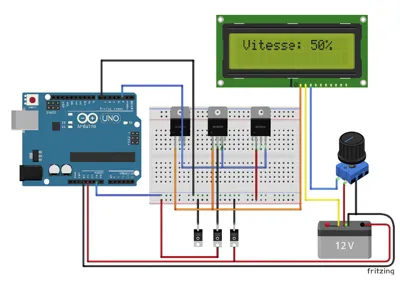
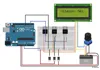
Arduino Implementation:
Three MOSFETs, a push-button potentiometer, a 16x2 LCD display, three 220–330Ω resistors (for MOSFET gates), and a 12C-compatible Arduino are required.
For Arduino power supply, utilize a 12V-5V buck converter or leverage the power jack with a 5V step-down regulator.
Arduino Code:
#include <Wire.h>
#include <LiquidCrystal_I2C.h>
// LCD configuration (I2C address 0x27, may vary)
LiquidCrystal_I2C lcd(0x27, 16, 2);
// Pins
const int potPin = A0; // Analog potentiometer
const int buttonPin = 2; // Potentiometer push button (digital)
const int motor1Pin = 3; // PWM Motor 1
const int motor2Pin = 5; // PWM Motor 2
const int motor3Pin = 6; // PWM Motor 3
// Variables
int potValue = 0;
int motorSpeed = 0;
bool motorsOn = false;
bool lastButtonState = HIGH; // Pull-up style button
unsigned long lastDebounceTime = 0;
unsigned long debounceDelay = 50; // Button debounce
void setup() {
// Pin initialization
pinMode(buttonPin, INPUT_PULLUP); // Internal pull-up button
pinMode(motor1Pin, OUTPUT);
pinMode(motor2Pin, OUTPUT);
pinMode(motor3Pin, OUTPUT);
// LCD initialization
lcd.init();
lcd.backlight();
lcd.setCursor(0, 0);
lcd.print("Launcher Ready!");
}
void loop() {
// Potentiometer reading
potValue = analogRead(potPin);
motorSpeed = map(potValue, 0, 1023, 0, 255); // PWM scaling
// Push-button reading (with debounce)
int reading = digitalRead(buttonPin);
if (reading != lastButtonState) {
lastDebounceTime = millis();
}
if ((millis() - lastDebounceTime) > debounceDelay) {
if (reading == LOW) { // Button pressed
motorsOn = !motorsOn; // Motor ON/OFF toggle
}
}
lastButtonState = reading;
// Motor control
if (motorsOn) {
analogWrite(motor1Pin, motorSpeed);
analogWrite(motor2Pin, motorSpeed);
analogWrite(motor3Pin, motorSpeed);
} else {
analogWrite(motor1Pin, 0);
analogWrite(motor2Pin, 0);
analogWrite(motor3Pin, 0);
}
// LCD display
lcd.setCursor(0, 1);
lcd.print("Speed: ");
lcd.print(map(motorSpeed, 0, 255, 0, 100)); // Percentage display
lcd.print("% ");
delay(100); // Minor delay for stability
}
🛠 Pre-upload Verification:
Hardware Specifications
LCD I2C I2C address typically 0x27 or 0x3F (scan if needed)
Potentiometer A0 for analog signal + digital pin (2) for button
MOSFET Ensure logic level compatibility (e.g., IRLZ44N) for proper 5V Arduino switching
Power Supply Utilize an external power source for motors, not the Arduino
🧩 Quick Schematic:
Potentiometer: center to A0, ends to 5V and GND. Button to D2 (with internal pull-up).
MOSFETs:
Drain → Motor
Source → GND
Gate → Arduino PWM pin via a 220–330Ω resistor
LCD connected to SDA/SCL (pins A4-A5 on Uno R4 or dedicated pins on your model)

MML Usage Declaration: (ChatGPT)
To expedite code generation and documentation, ChatGPT assisted in drafting parts of this description. Should the code malfunction (a possibility), I offer my sincerest apologies.
Documentation (7)


Comment & Rating (0)