Adapter V2 + Dualtron Rear Turn Signals


Print Profile(2)

Bill of Materials


- conector hembra 2 pines x 2:
- contecor macho 2 pines x 2:
- Cable DC 12v 2hilos x 2: 300mm
Description
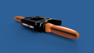
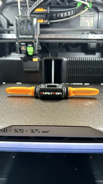
Dualtron Rear Turn Signal Adapter V2 + 12Vdc Sequential Turn Signals V1
This adapter is designed for installing additional turn signals on Dualtron brand electric scooters. I had chosen 12Vdc sequential motorcycle LED turn signals[1]. After some time using them, the rubber they are made of is not of very good quality and as a result, they break.
Therefore, I decided to redesign the entire assembly and take the opportunity to fix V1 failures, and this is the result
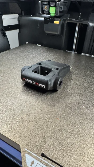
Body modified and redesigned to hide the cables that were visible over the shock absorber.

- The longitudinal distance has been reduced as it was hitting a lot when holding the scooter.
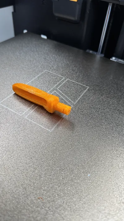
- The turn signals have been redesigned for printing in TPU Translucent and to reuse parts from the previous ones. However, a light diffuser (for printing in transparent PLA) is included in the file if one is not available.
- The following print profiles are added:
- Normal: 1 material with automatic tree supports.
- 2 Materials: with PETG interface supports for easy removal and 0.0mm separation to improve the quality of the supported area.

Parts:
- Printable:
- 1 x right turn signal
- 1 x left turn signal
- 2 x turn signal fixing clip
- 1 x main body
 2 x transparent light diffuser (optional if not available)
- Non-printable parts:
- 4 x M screw
- 2 x 12Vdc Orange Sequential LED Board
- 1 x 3-pin male JST connector (optional 4-pin)
- 1 x 3-pin female JST connector (optional 4-pin)
Assembly instructions:
Assemble turn signal parts (LED PCB, wiring, diffuser,…)

- Insert the turn signals into their designated slots in the adapter body and secure them with their locks (as per animation)
- Pass the cables through the lower guides designed for them.
- Connect the cables with JST terminals.
- Screw the adapter body to the scooter's shock absorber body.
- TEST!!!!
- ENJOY!!!

Why install this update/improvement on your scooter?
- Anticipating the movements of other urban road users is becoming increasingly complicated every day due to the speed at which everything is advancing. Therefore, this improvement allows us to indicate our intentions to other users so that they can react accordingly.
- It is well known that when riding an electric scooter on urban roads shared with other vehicles (cars, buses, vans, bicycles, pedestrians….), if there is no safe distance, it is impossible to see the light of the factory turn signals integrated into the chassis. Therefore, this design has been made to raise the angle of the rear turn signal light so that they are visible even from short distances from the vehicle in front of us.
- It also improves the visibility of these signals to people on sidewalks and...
- Considerably increases the safety of circulation with this type of vehicle.
- Reduces the risk of accidents caused by poor visibility of factory turn signals.
- The sequence clearly indicates the desired direction.
Printing notes:
- It is recommended to print the adapter body in PETG or ABS, as it withstands chemical agents, adverse weather conditions, and UV rays much better than PLA.
- If you don't have an AMS, you can print it in a single color.
- NO supports are needed for the adapter body.
- It is recommended to print the turn signals in TPU (translucent if possible)
- YES supports are needed for the turn signals (2 print profiles are attached: 1 and 2 materials)
- Print the turn signal fixings in the same material as the body.
- Make sure to clean your build plate.
Electrical installation notes:
- You will need 2 x 60-80Vdc to 12Vdc DC-DC converters.
- Locate and connect the two power cables of the right lamp to the DC converter and its output to the new turn signal lamp.
- Locate and connect the two power cables of the left lamp to the DC converter and its output to the new turn signal lamp.
- If you wish, you can cancel the factory turn signals as they will no longer be necessary.
Required parts:
- 4 x M5x25 screw
- 1 x male JST connector
- 1 x female JST connector
- 2 x Sequential LED Turn Signals (complete kit of 4)
(from this we will use its internal parts)


These turn signals were used in a first version of the adapter, but over time they broke and due to this, their parts (LED PCB board and transparent plastic diffuser) have been reused for the new version.
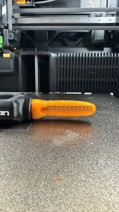
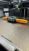
The result of the modification can be seen in the images below:


Commercial use of any of my designs is strictly prohibited. All my designs are available exclusively on my Makerworld profile.
[1] If desired, other types of LEDs can be used, such as 3Vdc or 5Vdc sequential or non-sequential COB LEDs. For this, 2 additional DC-DC converters will be needed, installed at the 12Vdc output
Boost Me (for free)
Documentation (1)
License
You shall not share, sub-license, sell, rent, host, transfer, or distribute in any way the digital or 3D printed versions of this object, nor any other derivative work of this object in its digital or physical format (including, but not limited to, publishing derivative works outside the Makerworld platform or hosting on other digital platforms). The objects may not be used without permission in any way whatsoever in which you charge money or collect fees. Subject to the above restrictions, derivative works may be published only within the Makerworld platform, and all such derivative works must be licensed under the same SDFL‑C license, without modification or additional terms. You may download the digital versions of this object, 3D print it, and display images, videos, or usage demonstrations of 3D printed versions of the object on personal social media platforms or Makerworld official channels, provided that no digital versions of the object are shared or distributed.
Comment & Rating (0)