Non-Circular Planetary Gear - Educational Model


Print Profile(1)

Description
My Educational Mechanical Examples Series
This model is one of my educational mechanical mechanism examples on 80mm x 80mm base plates.
You can find all models of the series in this collection => [Mechanical Mechanism Examples]

The present model
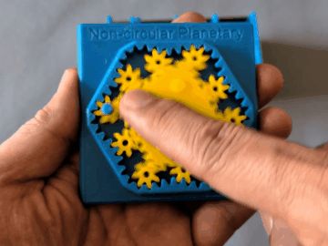
This is an educational model of non-circular planetary gear, where the planetary gear themselves are circular but the sun gear and the outer ring gear are non-circular.


Brief Description
In this model, circular planetary gears revolve around the center of a non-circular sun gear along a non-circular orbit, with a revolution speed that varies along the orbit. Specifically, the planetary gears move faster where the orbit's curvature is positive and slower where it is negative. As a result, the spacing between adjacent planetary gears along the orbit becomes not uniform.
The model was designed as follows.
- The pitch curve of the fixed outer ring gear is defined as a deformed circle whose radius is sinusoidally modulated six times per revolution.
- The orbit of the planetary gear centers is then determined by offsetting the outer ring's pitch curve inward by the planetary gear's pitch radius.
- The number of teeth on the outer ring gear is chosen to be 48, i.e., eight teeth per modulation period.
- The number of teeth on the sun gear is chosen to be 32. This is motivated by having the same number of teeth per modulation period as the outer ring gear: 48/6 = 32/4 = 8. As a consequence of the kinematic constraints, the sun gear's pitch curve develops 4-fold symmetry.
- The number of teeth on the planetary gear is chosen to be 7. If 8 were chosen instead, the standard circular planetary gear condition (z_outer = z_sun + 2 z_planetary: 32 + 2×8 = 48) would be satisfied, yielding a purely circular system. Choosing 7 — slightly fewer than this value — intentionally violates that condition and is what introduces non-circularity into the system.
- The pitch curve of the sun gear is then determined by imposing three conditions:
- The pitch circle of a planetary gear must roll against the pitch curve of the outer ring gear without slipping. This condition determines the planetary gear's spin angular velocity from its orbital velocity.
- The pitch circle of a planetary gear must also roll against the pitch curve of the sun gear without slipping, while the sun gear rotates about its axis. This condition yields a quadratic equation for the sun gear's angular velocity, and the contact point between the two pitch curves is then derived from the solution.
The perimeter of the sun gear's pitch curve must be 4/6 of that of the outer ring gear (equivalently, z_sun/z_outer = 32/48). This condition is satisfied by adjusting the modulation amplitude of the outer ring gear's radius.

- Once the pitch curves of all three gears are determined, the tooth profiles are generated by rolling a virtual rack-shaped cutter along each pitch curve, following the same envelope method used for conventional involute gear cutting.
- Ten planetary gears can mesh simultaneously with a single pair of sun and outer gears. Their meshing positions can be found by placing planetary gears one at a time at phases where the corners of the sun and outer gears coincide, while rotating the sun gear; this procedure yields ten in total.
From the model, you can see that the planetary gear completes one revolution while the sun gear rotates 2.5 turns. This is easily understood by rotating the model in your hands as follows. Place a planetary gear at a corner of the outer gear; it is then also at a corner of the sun gear. Rotate the sun gear until the planetary gear reaches the neighboring corner of the outer gear. During this motion, the planetary gear rolls along one edge of the outer gear and simultaneously along one edge of the sun gear. To do so, the sun gear must rotate by 90° + 60° = 150° (90° between adjacent corners of the 4-fold-symmetric sun gear, 60° between adjacent corners of the 6-fold-symmetric outer gear). To roll along all six edges of the outer gear, the sun gear must rotate by 150° × 6 = 900° = 360° × 2.5; this is why the sun gear must turn 2.5 times for the planetary gear to complete one full revolution.
Because the revolution speed of the planetary gear varies with the curvature of its orbit, the gaps between adjacent planetary gears vary substantially around the orbit. Exploiting this fact, this type of non-circular planetary gear system has been studied as a pump, somewhat analogous to a trochoidal pump. Its practical efficiency as a pump is unclear to me, but non-circular planetary gear pumps have been studied in the literature and reported to have advantages such as uniform flow and low noise. In any case, this model is at least an interesting and educational example of a gear system.
Reference
Related Models


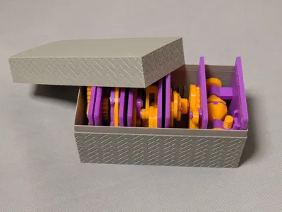
Case
This model is compatible with the case included in my first set.

Printing
- Use the models named ???-printable.stl for printing.
The models named ???-assembled.stl are provided just to show how they should be assembled.
- Use well-dried PETG to have better dimensional accuracy.
- Use 0.1 mm or 0.08 mm layer height to have smoother surfaces.
- Use slow printing speed for overhangs.
- Select “Random” seam position to have smoother rotation.
Randomly distributed seam should be easily worn out after some wearing.
Each planetary gear has a flange on its bottom face, with a diameter close to that of the gear's root circle. The flange overlaps axially with the tooth tips of the sun and outer gears, preventing the planetary gear from falling out of the gear system when the model is turned over. If you print planetary gear in different color from the base plate, it is a good idea to print the flange in the same color with the base plate as shown in this photo. This makes the planetary gear shape much clearer seen from the top.


To do this, you do not need to use AMS.
Instead insert a PAUSE command at the layer where you want to change the color and change the filament while the printing is paused.
Then resume the printing.
Sanding and Filing
Note that, in this model, the rotation of the bases for bearings is intentionally made not too smooth.
Sometimes, the gears suffer from the stringing effect and/or elephant foot effect, resulting in a too tight fit to the shafts (they are designed with a 0.15 mm radial clearance).
If you see rough surface on the shafts due to stringing, sand off the roughness with a small piece of sand paper.


If you feel the gears do not rotate smoothly due to an elephant effect, widen the hole slightly by using a thin round bar file.

Without those issues, the parts should rotate very smoothly with minimal friction.
Assembly
Each planetary gear has a flange on its bottom face, with a diameter close to that of the gear's pitch circle. The flange overlaps axially with the tooth tips of the sun and outer gears, preventing the planetary gear from falling out of the gear system when the model is turned over.
This flange also prevent you to insert the planetary gears after attaching the sun gear.
So, you have to put the planetary gears at the correct places before carefully inserting the sun gear.
This is some what tricky. You may need a few trials before success.
Refer to the photo below to find the correct places for planetary gears.

If you feel the gears do not rotate smoothly, try rotation with only one planetary gear.
Then you can feel which point is not ideal.
Examine the tooth shape around there and file off any debris on the surface or deformed part that prevent smooth rotation.
Updates
- 2026-06-07 Solves the negative backlash issue (v28)
- The previous version suffers from small interferences, because of the misconfigured negative backlash clearance. The new version rotates even much smoother without the issue.
Other examples
You may also be interested in the models in my educational mechanical mechanism examples.
Find them in this collection:
https://makerworld.com/collections/15048577-my-educational-mechanism-models
Happy printing!
Acknowledgement
I got into gears thanks to K.$uzuki's amazing articles and YouTube videos. Many of the mechanisms shown in this series came from the introductions on his website. He also makes excellent gear models himself. This series wouldn’t have existed without his inspiration.
I learned a lot about technical detail of designing gear tooth profiles from Haguruma-No-Hanashi website. I’m truly grateful for that.
License
- The 3D model(s) are licensed under Creative Commons Attribution 4.0 International.
- However, the text and images on this page are copyright reserved.
Comment & Rating (2)