Tripod v3 Side Arm /Photography Platform


Print Profile(5)
Description
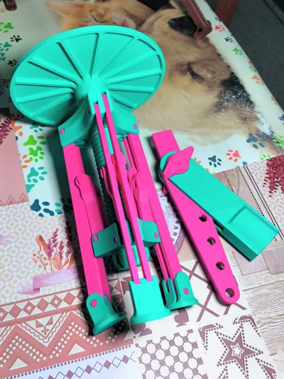
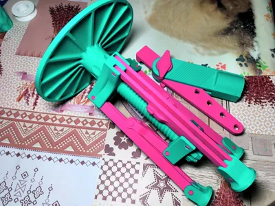
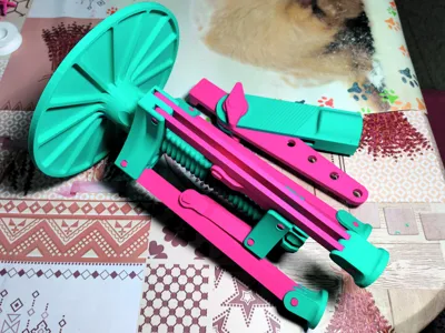
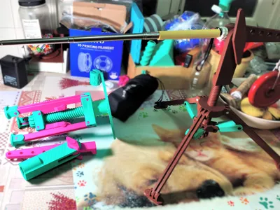
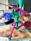
Tripod v3 Side Arm + Photography Platform
This model is the third iteration in the tripod family I have designed over the past year. I have applied the experience and specific needs I encountered, and the model has been improved in small details since its inception, reaching its optimal point a couple of months ago. Even so, I had not published it yet, wanting to see how it performed over time, with daily use, and for particular tasks.
Features:
- Design.- Its design is intended to be versatile, comfortable, functional, efficient and practical for any required task. It comes with several adapters that increase its versatility for practical work with various tools.
- Functions.- Functions to be performed are:
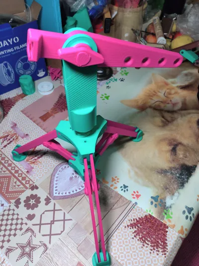
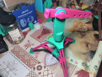
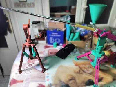
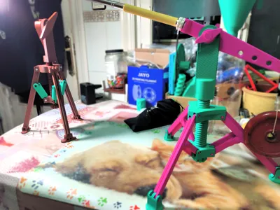
- Tripod.- Its main function, although it also has adapters for extra tasks. Its main virtue is to keep everything stable without flinching, which it does perfectly due to its 3 support points and with its wide opening, it can hold a 1.5m extendable rod without swaying.
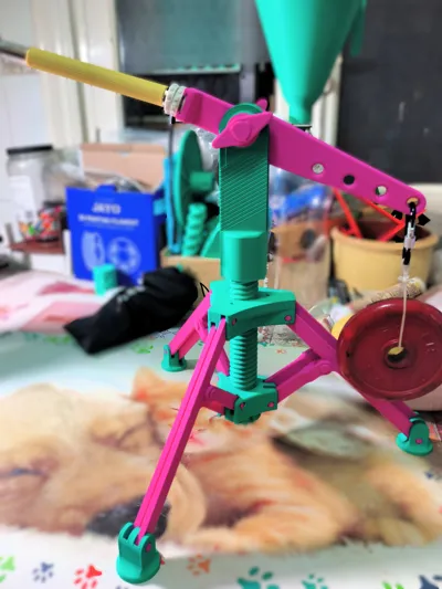
- Adjustable Side Arm.- The spread of its legs when unfolded provides a large area that distributes the load, as well as great torsional resistance due to the extension that protrudes from the body, acting as a lever. For this reason, the adapter has holes to hang a 1 kg counterweight.
- Photography Base.- The weight it must support for extended periods is evident. For certain tasks, thought was given to how to best distribute the load, avoiding unnecessary damage and breakage. In tests, it has supported a load of around 5kg without flinching.
Mobility Modification.- This is a subtle modification that allows for the incorporation of swivel wheels on the tripod; however, these are still in the testing phase. It also requires 22x8mm bearings.
- Types of Adapters.- Currently, the model consists of 4 adapters and one modification:
- 1/4 inch Adapter.- for screws used in most photography accessories
- Quick Change Adapter.- This component is currently used, its dimensions are (18x18mm).
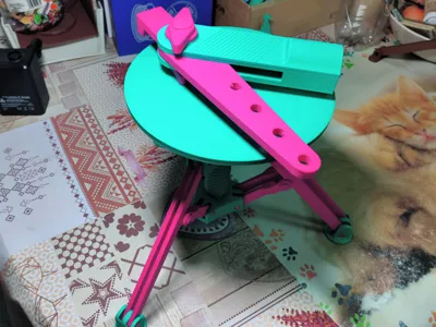
- Adapter - Adjustable long arm.- It has a quick-release connector at its end and allows its height and distance to be adjusted thanks to its adjustment screws.
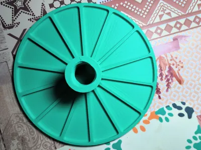
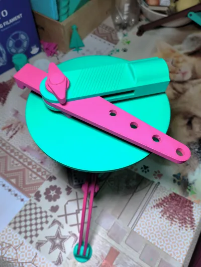
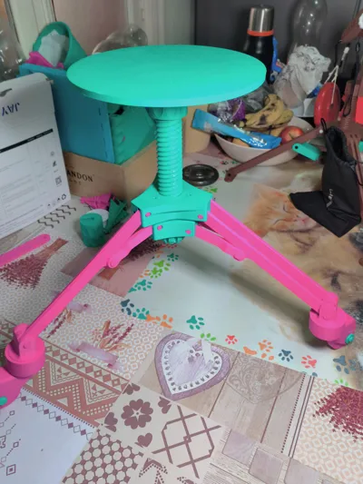
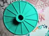
- Adapter - Photography platform.- It is a flat surface 20 cm in diameter for taking photos of objects.
- Swivel Wheel Modification.- Allows for the incorporation of wheels that move 360 degrees.
- Size.- The model has two positions: unfolded, which is in working mode, and folded, which is at rest:
- Unfolded.- Its legs, when at their maximum spread, have an approximate diameter of 60 cm.
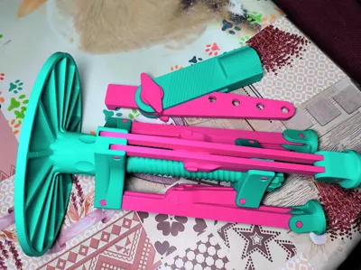
- Folded.- will depend on whether or not the "photography base" adapter is used, which has a diameter of 20cm, and without it, it does not exceed 10cm in diameter.
- Note: its opening can be varied depending on the use; it is not necessary for it to be fully unfolded.
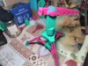
- Portability.- It is highly portable, being a lightweight and ultra-compact model that can be carried or stored in a bag or backpack without issue. Additionally, being a modular and detachable model, it assembles with relative ease.
- Working Area.- the space required for its operation is relatively large; everything will depend on the task being performed and the available space. The minimum space required to prevent falls and loss of balance is 20 to 30 cm.
- Durability.- Durability has been a fundamental pillar in this model. For this reason:
- The model took time to be released from its design and printing date.
- Its biggest flaw is its greatest virtue, which is being a printed model. As it is made of fused plastic, there are small joints, protrusions, or parts that experience extreme stress. With this in mind, the goal was to increase their resistance to extreme situations they might face.
- Most importantly, it should be clarified that it is a fully 3D printed model that particularly requires no extras except for two optional M3 screws.
- Its design and completeness provide an extra bonus of resistance against unusual activities.
- Certain materials can provide extra resistance values against weather, wear, stress, temperature, and weight. Choosing the best one is the optimal option for this model.
- NOTE: It is recommended that the parts called pins, which are the axis of the moving parts, be printed in high-resistance materials such as PETG, ABS, or ASA.
Boost Me (for free)
If you liked the model's design and appreciate the effort put into bringing it to you, support me with a boost
Printing Features:
Recommended Filament: PLA (PETG for pins part 10,11,12 and mod part 25 and 27).
Tolerance: 0.2mm
3 Walls 10% infill.
Supports Yes Normal (On the legs).
LIST OF MAIN PARTS
| No. in model | Part Name | Parts Required |
| Part 1 | Main Body - Base | 1 |
| Part 2 | long right arm | 3 |
| Part 3 | long left arm | 3 |
| Part 4-7 | Main body - threaded screw | 1 |
| Part 5 | short right arm | 3 |
| Part 6 | short left arm | 3 |
| Part 8 | crank | 1 |
| Part 9 | legs | 3 |
| Part 10 | pins A | 12 |
| Part 11 | pins C | 6 |
| Part 12 | pins B | 6 |
| Part 20 | Reinforcement bar | 1 |
LIST OF ADAPTERS
| No. in model | Part Name | Purpose |
| Part 14 | screw adapter | for 1/4 inch screws |
| Part 15 | quick adapter | 18x18mm systems |
| Part 16-17-18-19 | long L arm | extendable lighting bars |
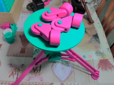
| Part 21 | photography base | 20cm diameter circular base |
Partial explanation of the components required for assembling the tripod.
Short arms.- These are identified as Part 5 and Part 6. As can be seen in the image, these are 3 pairs that are slightly attached to each other. They can be easily identified by their shape. Part 5 is the right one and Part 6 is the left one.

Long Arms.- these are Part 2 and Part 3. There are 6 of these, similar in both shape and assembly.

Main Body.- This assembly consists of 2 main parts: Part 1, which is the base that holds the threaded "nut", and Part 4-7, which are actually two pieces that function as one. It should not be separated in the slicer.
NOTE: when printing Part 4-7, the 0.2mm tolerance already in the model must be considered. Once printed, it may be slightly stuck and needs to be freed with small left and right movements.

The legs are identified as Part 9 and the adjustment crank as Part 8.

In the main model, 3 types of pins are used, and the wheel mod uses a single model:
- Pin A (Part 10).- These are responsible for connecting the long and short arms to the main bodies.
- Pins B (Part 12).- Their sole purpose is to connect the long arms to the model's legs.
- Pins C (Part 11).- Likewise, their sole purpose is to connect the short arms to the long ones.
Pins D (Part 25-27).- These are part of the mod and are only necessary for it. They are not in the main model.

NOTE: to differentiate them, it can be seen that pins A have no head or protrusions, pins B have a small head, and pins C have a large head.
Tripod Assembly
1) First, place the short arms: these consist of 3 pairs, left and right, as shown in the photo. (the more protruding parts should go outwards and the thinner parts inwards on the model)

2) Second, place pins A into the holes. These have a small notch that matches the hole where they should go.
IMPORTANT: once assembled, it is difficult to remove them, so be careful when assembling.

3.1) Upper body assembly. For ease of assembly, the two main parts should be assembled separately.

3.2) Place the long arms into the holes; as they are identical, this is not complicated.
IMPORTANT: the middle hole must face upwards and inwards on the model so that it can be secured to the short arms.


3.2) The placement of pins A is the same as step 2.
NOTE: use a protruding surface for more comfort and ease.

4.1) When attaching the legs, the indentations must face inwards on the model so that it can unfold easily.

4.2) In this case, Pins B (Part 12) are used. These also have a notch that guides the orientation, plus a small head that allows them to be easily removed.
Note: Do not confuse them with pins C, which have a larger head.

5) Main body assembly: for this, the screw must be threaded into the main base until the holes of the short arms and long arms are aligned.

5.1) When attaching pins C, follow the orientation of the notch on the short arms.
NOTE: be careful when doing this, as the arms can move.


6) The adjustment crank has a shape and design that fits the hole in the base of the threaded screw.

NOTE: In this case, the screws are optional and can be secured to the holes with glue.

7) The reinforcement bar is essential to provide rigidity and flexibility, preventing cracks due to excessive bending of the threaded screw.


L-Arm Assembly
To use the adapter, it is important to know that a quick-slide system adapter is required.
The Adapter consists of different parts to function correctly:
| No. in model | Part Name | Parts Required |
| Part 16 | L Adapter | 1 |
| Part 17 | Pivoting arm | 1 |
| Part 18 | adjustment screw | 1 |
| Part 19 | tightening nut | 2 |

1) First, place a nut on the tightening screw. This step is done on both sides of the screw.

2) Place the pivoting arm inside the arm adapter and center the hole of the two models.

3) Place the second nut on the tightening screw.
Note: Remember that the adapter has a pronounced hole where the pivoting arm slides down and enters.

Photography Platform
This is Part 21 within the model.

Documentation (4)
License
You shall not share, sub-license, sell, rent, host, transfer, or distribute in any way the digital or 3D printed versions of this object, nor any other derivative work of this object in its digital or physical format (including - but not limited to - remixes of this object, and hosting on other digital platforms). The objects may not be used without permission in any way whatsoever in which you charge money, or collect fees.
Comment & Rating (0)