Minecraft Lantern


Print Profile(1)

Description
Description
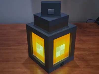
This Minecraft lantern began as a science project for my daughter to explore the fundamentals of electrical circuits. Originally housing a simple battery-powered circuit she built for her science class, I later upgraded the design to support both battery and USB-C power. It’s an ideal project for anyone looking to create a functional light source that works perfectly as a cozy accent or a night light.
NOTE: I've included a plate with the side panel that can be printed with an AMS, and another plate of the side panel that can be printed in one color. The entire lantern can be printed without an AMS.
Electrical Components
I chose a 9-volt setup for this lantern so it can run on either a standard 9V battery or a USB-C connection. The USB-C component is specifically configured to pull 9V to match the circuit. You can find the exact parts I used listed below, but feel free to source your own if you prefer different brands or local suppliers.
NOTE: I’ve kept the base/bottom plate as an un-merged component to make it easy for you to customize your own circuit. If you want a battery-only or USB-C power-only setup, it's easy to modify the internal components to suit your specific needs.
- USB-C 5V-20V Power Delivery Module
- Uninterrupted Power Supply (UPS) Module 5V-48V
- LED Screw-Mount E10 Small Bulbs Holder with Wire Socket
- ON and Off Rocker Switch
- 9 Volt Battery Connector with Wire Leads
- AC/DC E10 LED Light Bulb
- Rechargeable 9V Lithium-Ion Batteries
- USB-C Fast Charging Multi-Port Adapter
- 3ft USB-C to USB-C Fast-Charging Cable
- Wire Lever Nuts
Additional Required Items
Assembly Instructions
Using super glue, secure the four corner posts to the bottom layer. Ensure the slots on each post align perfectly with the grooves in the base. Once the glue has set, slide the four side panels into their respective slots; no glue is required for these panels. Please refer to the image below to ensure the panels are oriented correctly.
IMPORTANT: Press the M3 nuts into the four holders located in the interior corners of the base. It is highly recommended to do this now; seating the nuts becomes much more difficult once the rest of the lantern is assembled.


Using super glue, secure the three top-layer pieces to each other. Then, secure the handle piece to the top-most layer.


Using super glue, secure the top half assembly and the bottom half assembly.


Tilt the lantern assembly on its side to access the bottom cavity. Attach the rocker switch to its compartment by sliding it in from the outside edge. The switch has its own supports to secure itself in place by pushing it into its compartment.


Slide the USB-C power delivery module into its designated compartment from the interior edge. Once seated, snap the module clip into place; this acts as a backstop to prevent the module from being pushed inward when you plug in a cable.
IMPORTANT: Ensure that the three switches are configured properly for 9 volts if you are following the same setup. If you are creating your own circuit, make sure the three switches match the voltage output your circuit expects.


Secure the bulb holder to the base plate. To maintain a clean interior, route the wires through the wire organizers located around the center to prevent them from shifting.
NOTE: Be sure to use the wire organizers; otherwise, loose wires might cast visible shadows through the side panels when the lantern is powered on.


Attach the connector to the 9V battery and seat it within its housing. Guide the wires through the wire organizers to ensure they stay away from the light source.


Slide the UPS module into its designated housing and connect the battery leads. Ensure the positive wire is secured to the positive (+) terminal and the negative wire to the negative (-) terminal on the UPS module.


Attach the USB-C power delivery module wiring to the UPS module's direct current (DC) terminals. Ensure the positive wire is secured to the DC positive (+) terminal and the negative wire to the DC negative (-) terminal on the UPS module.


Attach the negative wire coming from the bulb holder(the green wire in my case) to the negative output terminal on the UPS module.


Connect one lead from the rocker switch to the positive output terminal on the UPS module. As shown in the photos below, I extended this wire slightly to ensure it reached the terminal comfortably. Next, connect the second wire from the rocker switch to the positive lead on the bulb holder. I used a lever nut to ensure all wire connections are both secure and easy to manage without the need for soldering. Your circuit is now complete. When securing the base plate to the lantern assembly, ensure all wiring is tucked neatly below the bulb to avoid any interference or shadows.


Boost Me (for free)
If you're feeling generous, any boosts you send my way are super appreciated. They directly help me buy more filament, which means I can keep creating and uploading even more models for everyone to enjoy. Thanks for your support!
License
You shall not share, sub-license, sell, rent, host, transfer, or distribute in any way the digital or 3D printed versions of this object, nor any other derivative work of this object in its digital or physical format (including - but not limited to - remixes of this object, and hosting on other digital platforms). The objects may not be used without permission in any way whatsoever in which you charge money, or collect fees.
Comment & Rating (0)