Search models, users, collections, and posts
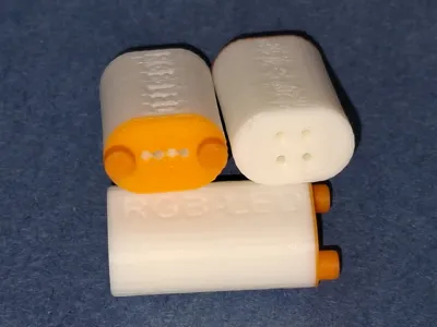
Bending tool RGB led
IP Report


Print Profile(1)

Bending tool printed with 0.2mm nozzle
Designer
44 min
1 plate
Open in Bambu Studio
Boost
29
59
1
0
21
10
Released
Description
Content has been automatically translated.
German | English |
|
|
German
- For my project to illuminate a glass brick wall using LEDs with an integrated WS2812 controller, I had to solder a lot of wired LEDs into breadboards.
- These LEDs, regardless of whether they have a diameter of 5 mm or 8 mm, have four small, very thin, and very sensitive legs, also known as connecting wires.
- These fine pins are spaced 1/20" apart, which is 1.27 mm.
- However, in the breadboard, the pads are spaced 1/10" (2.54 mm) apart.
- So if you want to insert and solder one of these LEDs into the breadboard, you first have to bend the delicate legs into the appropriate grid.
- This is a lot of work and requires a high degree of fine motor skills (I always say, “you need fingers like a female chaffinch”).
- It almost goes without saying that a pin may occasionally fly off during the correction bending process.
- But as a hobby inventor, there is something you can do about it.
- Now there is the long-awaited tool that relieves me, and soon you too, of this tedious process.
- Usage:
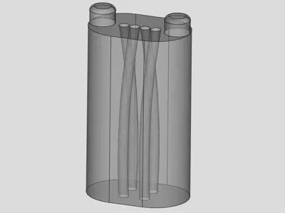
- Insert the component with the 4 parallel pins into the top of the bending aid.
- Push it in as far as it will go.
- Pull it out again and now insert the pre-bent pins on the other side of the bending aid into the holes that now fit. This will make the pins, which are bent at 1/10" intervals, more parallel, which makes it easier to work with them on the circuit board.
- The insertion depth depends on the desired installation depth in the circuit board. My recommendation: leave a gap of about 3 mm, otherwise the stress caused by bending could lead to problems.
- 3D printing:
- Please use the 0.2 mm nozzle and print the first 3 layers and the upper part of the bending aid in a different color (for better visibility of the holes).
- If printing without AMS, the two surfaces can also be colored by hand.
License
This user content is licensed under a Standard Digital File License.
You shall not share, sub-license, sell, rent, host, transfer, or distribute in any way the digital or 3D printed versions of this object, nor any other derivative work of this object in its digital or physical format (including - but not limited to - remixes of this object, and hosting on other digital platforms). The objects may not be used without permission in any way whatsoever in which you charge money, or collect fees.
Comment & Rating (1)